
Related Manuals for VTS Medical Systems Ventus Compact VVSc Series


Summary of Contents for VTS Medical Systems Ventus Compact VVSc Series
- Page 1 & P AHU Q UICK TART UIDE VVSc Floor-mounted Compact Units VVSs Ceiling-suspended Compact Units VTS Technology Department Rev: 2020-04-30...
-
Page 2: Table Of Contents
Table of Contents General safety rules ............................. 2 About this quick step manual ..........................3 Range of covered information ........................3 4 steps to run your Air Handling Unit......................3 Stage 1 – unboxing of the control elements ..................... 3 Stage 2 –... - Page 3 Connection to mains ..........................17 VVS0005cs – VVS030s – Ceiling Suspended Compact Air Handling Unit ........... 18 Power supply cables ..........................18 Connection to mains ..........................18 Air Handling Unit start-up ..........................19 Switching on the Air Handling Unit ......................19 Start-up by means of the HMI Basic ......................
-
Page 4: General Safety Rules
GENERAL SAFETY RULES Before attempting to any works described in this Quick Set-Up Manual and other related documents please acknowledge below listed General Safety Rules: All installation, configuration and start-up work described in the following chapter of this manual and the related ones must be done by authorized personnel and with respect to code of the state in which the installation of the unit is done. -
Page 5: About This Quick Step Manual
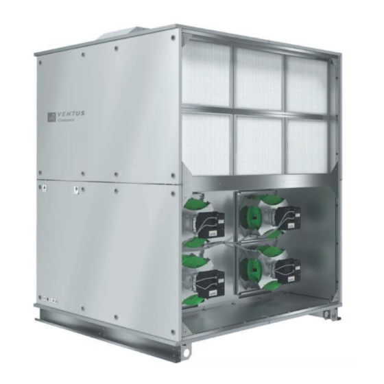
ABOUT THIS QUICK STEP MANUAL ANGE OF COVERED INFORMATION This document is a quick installation, configuration and start-up manual for the following range of VTS Products (Figure 1): VVSc Floor-mounted Compact Units VVSs Ceiling-suspended Compact Figure 1 - VVSc and VVSs range of Air Handling Units It is aimed to guide the user through all necessary steps, systematize the sequence of taken actions to prevent from any damage to the equipment while setting-up the AHU. -
Page 6: Stage 4 - Start-Up Of The Air Handling Unit
4 – S TAGE TART UP OF THE ANDLING Details in chapters: Air Handling Unit start-up REFERENCE MANUALS In the following chapters of this Quick Set-Up Manual, multiple references to detailed manuals of VVSc and VVSs ranges will occur. The full list of the reference manual has been listed below with the links: ... -
Page 7: Vvss Ceiling-Suspended Compact Units
VVSc unit factory fitted for Outdoor installation VVSc unit factory fitted for Indoor installation Figure 2 - VVSc - location of the terminal box EILING USPENDED OMPACT NITS The VVSs Floor-mounted AHU may be factory-fitted indoor application only. Depending on the execution, location of the terminal-box may vary, as per below (Figure 3): VVSs unit –... -
Page 8: Plug & Play Control Elements
Depending on the AHU execution (due to constant product improvement), terminal box of the VVSs Ceiling Suspended Compact Unit may occur in one of below modes: Terminal box includes main switch, mains and controls terminals only. Main AHU controller installed inside the unit’s body (Figure 3, left). -
Page 9: Connecting Of The Peripheral Control Elements To The Base Unit
Optional monitoring of returning heating water Strap-on return water temperature temperature, as an alternative to default heater sensor (for water heater) protection realized by means of anti-freeze thermostat Optional monitoring of CO concentration in return air concentration transducer supporting air mixing (VVSc base with mixing box) Optional monitoring of air relative humidity in the Relative Humidity Limiting supply duct to prevent against excessive humidity... -
Page 10: Air Damper Actuator
Figure 8 - Fire alarm signal connections / permanent bridge. Ports: Fire al. IR DAMPER ACTUATOR VVSc or VVSs supply-exhaust air handling units are equipped with two air dampers – one for supply, the other one for exhaust air tier. Both of the dampers are power supplied and controlled from the same location on the terminal block. The damper actuators will be connected to the Ports: Dampers G, Dampers G0, D02 of the switchboard. -
Page 11: Strap-On Temperature Sensor On Heating Water Return
Figure 10 - Connection of the antifreeze thermostat on the air side; Port: Heater al. G0, DI2 TRAP ON TEMPERATURE SENSOR ON HEATING WATER RETURN Strap-on temperature sensor (Figure 11) is an optional equipment of the water heater. While installing the strap-on temperature sensor, mind, that the sensor must be stuck to the return water pipe from your water heater. -
Page 12: Heating Water Circulation Pump
Figure 12 - Connection of the 3-way valve (part of the pump group) supply and control signal; Heating port EATING WATER CIRCULATION PUMP The heating water circulation pump (part of the water pump group) supports the 3-way valve in capacity regulation. It needs to be supplied with power. -
Page 13: Crossing And Connecting The Power Supply And Control Cables
Table 2 - power supply cables for electric heaters Heater Capacity Rated current Cable cross-section 3 kW 4,3 Amp 4 x 1,5 mm² 6 kW 8,7 Amp 4 x 1,5 mm² 9 kW 13,0 Amp 4 x 1,5 mm² 12 kW 17,3 Amp 4 x 2,5 mm²... -
Page 14: 3-Way Valve For Water Cooler
Control signal cable – will be crossed by the control gland (the small one) and connected to the X1 terminal block (Figure 14). NOTE! For unit with electric heater, the terminals of the water heater antifreeze thermostat must be permanently bridged, like shown on Figure 15. -
Page 15: Hmi Advanced
HMI A DVANCED HIM Advanced – an advanced user interface, enabling all range of AHU regulations and settings. Connect this interface using original cable terminated with RJ45 plug, as shown on Figure 17. Figure 17 - HMI Advanced port HMI B ASIC The HMI Basic interface enables basic range of AHU regulations and settings. -
Page 16: Connecting Of The Auxiliary Devices
CONNECTING OF THE AUXILIARY DEVICES HILLING SOURCE FAILURE ALARM For the unit equipped with cooler (both water or DX) you can connect a binary signal informing about general failure of the cooling medium source (chiller or DX compressor). If such alarm is triggered, the control application of the Air Handling Unit disengages the cooling mode (unit will remain running, with no cooling function). -
Page 17: On-Off Dx Compressor Start Permission Signal - Cooling Mode Only
Figure 22 - DX compressor failure status binary signal – COMPRESSOR START PERMISSION SIGNAL COOLING MODE ONLY For older types of DX compressors non-supporting capacity smooth regulation, a start permission signals can be output like shown on Figure 23. The system can output two signals: ... -
Page 18: On-Off Dx Compressor Start Permission Signal - Cooling And Heating Mode
Figure 24 - 0-10 V analog signal output for DX compressor - cooling and heating mode – COMPRESSOR START PERMISSION SIGNAL COOLING AND HEATING MODE For older types of DX compressors non-supporting capacity smooth regulation, a start permission signals can be output like shown on Figure 25. -
Page 19: Connecting The Air Handling Units To Mains
Figure 26 - Heating/Cooling mode information binary signal output CONNECTING THE AIR HANDLING UNITS TO MAINS Caution Before attempting to connect the Air Handling Unit to the mains, ensure that all peripheral devices are connected, and the main power switch is in OFF position. –... -
Page 20: Vvs0005Cs - Vvs030S - Ceiling Suspended Compact Air Handling Unit
Figure 27 - VVSc Floor mounted Compact Air Handling Unit - connection to mains, 3x400V AC – VVS030 – C VVS0005 EILING USPENDED OMPACT ANDLING OWER SUPPLY CABLES The power supply cables are not provided by VTS. Before attempting to the connecting the unit to the mains, ensure that you are supplied with correct type of cable and minimum length of it. -
Page 21: Air Handling Unit Start-Up
AIR HANDLING UNIT START-UP WITCHING ON THE ANDLING Before first switching on of your Air Handling Unit, verify all previously done actions with below check-list: Air Handling Unit is connected to the ducts Air Handling Unit is connected to the heating and cooling media sources ... -
Page 22: Running The Ahu
UNNING THE To run your unit (start your fans to spin) in the manual mode, press button located in right-upper corner of the HMI Basic interface. This will change the mode of your unit to Low fan speed. Press the button again and again to change the AHU mode between Low-Medium-High-Auto and Off mode. -
Page 23: Toggling Between Operational Modes
OGGLING BETWEEN OPERATIONAL MODES The HMI Advanced enables to toggle between various operational modes, like the ones available from HMI Basic interface. To toggle between the modes, do the following. Ensure that your HMI Advanced is displaying the main menu. You can press the Esc button few times, until you observe no changes on the display. - Page 24 Select the operational mode you want to modify – to do it toggle between them using Enter button ( ). Use arrows keys to change the value of the temperature settings and approve the changes by pressing Enter button ( ). Figure 38 - Air temperature settings for each mode...
-
Page 25: Appendix A: List Of Illustrations
APPENDIX A: LIST OF ILLUSTRATIONS Figure 1 - VVSc and VVSs range of Air Handling Units ......................3 Figure 2 - VVSc - location of the terminal box ........................... 5 Figure 3 - VVSs - location of the terminal box ........................... 5 Figure 4 - Required control elements for key air treatment functions ..................
Need help?
Do you have a question about the Ventus Compact VVSc Series and is the answer not in the manual?
Questions and answers