VTS Medical Systems VVS005s Operation And Maintenance Manual
Power slices
Hide thumbs
Also See for VVS005s:
- Quick start up manual (25 pages) ,
- Operation and maintenance manual (46 pages) ,
- Installation operation & maintenance (119 pages)

Related Manuals for VTS Medical Systems VVS005s


Summary of Contents for VTS Medical Systems VVS005s
- Page 1 Electric Heaters - Power Slices Operation and Maintenance manual VTS reserves the right to implement changes without prior notice OMM_HE_SEC_ver 1.1...
-
Page 2: Table Of Contents
Table of Contents Installation options ....................................1 Electric heater in the non-insulated duct ........................... 1 Power slices in original AHU casing ............................1 Range of the application ..................................1 VVS Standard & AVS ................................... 1 VVSc compact floor mounted air handling unit ......................... 1 VVSs suspended compact air handling unit .......................... -
Page 3: Installation Options
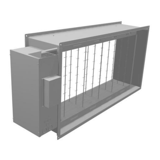
Installation options For the following AHU ranges: VVS Standard, AVS (with all subranges) and VVSc floor mounted units, the electric heater made of power slices can be applied in two different ways: Electric heater in the non-insulated duct As per default, the electric heaters made of power slices will be available as shown on the rights. All power slices will be simply installed in the short duct with the power junction box on the side. -
Page 4: Ssr Control
Total power power Slice qty power power power Slice qty power Device [kW] [kW] [kW] [kW] [kW] [kW] 1,25 VVS005s VVS010s VVS015s VVS020s VVS030s VVS021c VVS030c VVS040c 1,5 / 2,0 VVS055c 1,5 / 2,0 VVS075c VVS100c VVS120c VVS150c VVS021 VVS030... - Page 5 VVS650 NVS23 NVS39 NVS66 NVS80 High power L1/L2/L3 L1/L2/L3 Total power Control Current: wire 1 Current: Device [kW] box type wire 2 [A] VVS005s 1x18 21,6/12,5/12,5 VVS010s 1x18 26/15/15 VVS015s 1x18 26/26/26 VVS015s 2x18 52/52/52 VVS020s 1x18 26/26/26 VVS020s 2x18...
- Page 6 1x18 26/26/26 NVS80 2x18 52/52/52 NVS80 4x18 52/52/52 26/26/26 Low power L1/L2/L3 Total power Control Current: wire 1 Device [kW] box type VVS005s 1x18 6,3/6,3/0 VVS010s 1x18 7,5/7,5/0 VVS015s 1x18 8,7/8,7/8,7 VVS020s 1x18 8,7/8,7/8,7 VVS030s 1x18 8,7/8,7/8,7 VVS021 1x18 8,7/8,7/8,7...
-
Page 7: Electrical Supply System Details
VVS180 1x18 17,3/17,3/17,3 VVS230 1x18 17,3/17,3/17,3 VVS300 1x18 17,3/17,3/17,3 VVS400 1x18 17,3/17,3/17,3 VVS500 1x18 17,3/17,3/17,3 VVS650 1x18 17,3/17,3/17,3 NVS23 1x18 8,7/8,7/8,7 NVS39 1x18 8,7/8,7/8,7 NVS65 1x18 8,7/8,7/8,7 NVS80 1x18 8,7/8,7/8,7 Electrical supply system details TN system rated supply voltage 3x400V insulation rated voltage 400V rated impulse withstand voltage... -
Page 8: Electrical Connection
Electrical connection Connecting power supply should be carried out with a separate switchgear, not supplied with the VTS package. Connection of the heater should be done in a way to prevent from possibility of switching on the heater when the fan is not switched on. What is more, if the fan stops, the heater's power supply must be turned off as well. -
Page 9: Wiring Cable Types Details
Wiring cable types details Power cord for electric heaters (voltage 3 ~ 400VAC) Multi-core, copper conductor - twisted cable Operating voltage U0 / U 450 / 750V Working temperature -30- + 60C Power cable for the control system (voltage 1 ~ 230VAC) Multi-core, copper conductor - twisted cable Working voltage U0 / U 300 / 500V Working temperature -30- + 60C... -
Page 10: Wiring Schematics
Wiring schematics High power and low power box contains the same elements – only difference is in the connection of the heaters. Electric heater supply wiring should be let through the fixed panel, at the AHU's back. If the wiring is led through the inspection panel, on the front side, then it should be arranged so as to enable opening the section for maintenance and service operations. -
Page 11: 1X18Kw High Power
1x18kW High power VTS reserves the right to implement changes without prior notice OMM_HE_SEC_ver 1.1... -
Page 12: 1X18Kw Low Power
1x18kW Low power VTS reserves the right to implement changes without prior notice OMM_HE_SEC_ver 1.1... -
Page 13: 2X18Kw High Power
2x18kW High power VTS reserves the right to implement changes without prior notice OMM_HE_SEC_ver 1.1... -
Page 14: 2X18Kw Low Power
2x18kW low power VTS reserves the right to implement changes without prior notice OMM_HE_SEC_ver 1.1... -
Page 15: 4X18Kw High Power
4x18kW High power VTS reserves the right to implement changes without prior notice OMM_HE_SEC_ver 1.1... -
Page 16: 4X18Kw Low Power
4x18kW Low power VTS reserves the right to implement changes without prior notice OMM_HE_SEC_ver 1.1... -
Page 17: 6X18Kw High Power
6x18kW High power VTS reserves the right to implement changes without prior notice OMM_HE_SEC_ver 1.1... - Page 18 VTS reserves the right to implement changes without prior notice OMM_HE_SEC_ver 1.1...
-
Page 19: 6X18Kw Low Power
6x18kW Low power VTS reserves the right to implement changes without prior notice OMM_HE_SEC_ver 1.1... - Page 20 VTS reserves the right to implement changes without prior notice OMM_HE_SEC_ver 1.1...
-
Page 21: Maintenance Procedure
Maintenance Procedure Electric heater consists of bare heating coils. During AHU operation, when the heater does not work, dust may settle onto the heating coils. Once the heater is turned on again, strong contamination may cause smell of burning dust or even preliminary fire danger may appear. Check regularly (every year) and especially before starting a heating period, any electric connections, condition of heating elements and their contamination level.
Need help?
Do you have a question about the VVS005s and is the answer not in the manual?
Questions and answers