
Subscribe to Our Youtube Channel
Related Manuals for VTS Medical Systems VENTUS


Summary of Contents for VTS Medical Systems VENTUS
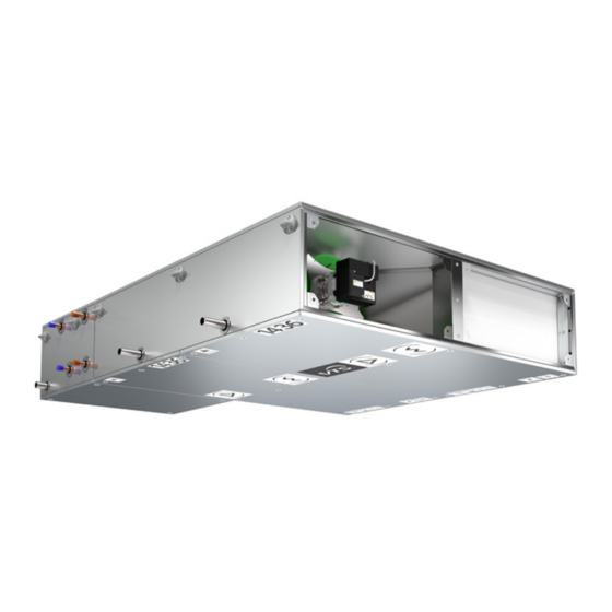
- Page 1 Operation and Maintenance Manual VENTUS Suspended Air–Handling Units Rated air flow range 400 – 1600 m3/h OMM–VVS–ver.1.6 (05.2018) www.vtsgroup.us...
-
Page 2: Table Of Contents
Table of content Warming, Cautions and Notices ..............6 Model Descriptions ..................7 General Information ..................8 Pre–Installation .................... 11 Transport and storage ................11 4.1.1 Receiving Checklist ................. 11 Installation Preparation ................12 4.2.1 Unit Location Recommendations ............ 12 4.2.2 Assembly in suspended position ............. - Page 3 5.2.6 Indication od operating mode ............30 System operation ................... 31 5.3.1 Operating mode ................31 Calendar ....................31 5.4.1 Calendar – Main page ..............31 5.4.2 Calendar – Day (Monday) ............... 32 5.4.3 Calendar – Special ................32 5.4.4 Calendar –...
- Page 4 5.6.15 Settings – Pressure regulators ............40 5.6.16 Settings – Temperature regulators ..........40 5.6.17 Settings – Manual mode ..............41 5.6.18 Settings – Frequence converter RRG ..........42 5.6.19 Settings – Fans fire mode ............... 42 5.6.20 Settings – Universal regulator ............42 Alarm menu ...................
- Page 5 Filters ..................... 64 Heat exchangers ................... 64 8.3.1 Water heater ................... 64 8.3.2 Electric Heater ................65 8.3.3 Water cooler ..................65 8.3.4 Freon cooler and heater ..............65 8.3.5 Counter flow heat exchanger ............65 Silencer section ..................66 Fan unit ....................
-
Page 6: Warming, Cautions And Notices
In–depth familiarization with the content of this manual, assembly, start–up and operation of the air handling unit in line with the instructions provided and following all safety regulations will ensure the basis of efficient, safe and non–failure operation of the device. This operation and maintenance manual does not cover all possible variants of the unit’s configurations, examples of their assembly and installation as well as start–up, operating, repairing and maintenance. -
Page 7: Model Descriptions
400–1600 m3/h. The VENTUS process starting from the simplest supply and air–handling units are designed for a exhaust to conditioning the supplied air in the... -
Page 8: General Information
General Information VVS suspended units are manufactured in The majority of AHU’s configuration is available sections designed for assembly in suspended in left–hand and right–hand execution (example configurations. All VVS AHUs are intended for in the fig.2). The version of the unit is indoor use, for cooperation with a duct determined by the flow direction of the air ventilation system. - Page 9 Fig.3. Example of the basic supply–exhaust unit (FPV) with additional coils section (HC): 1 – filters, 2 – counter–flow heat exchanger, 3 – fans, 4 – heater, 5 – cooler, 6 – droplet eliminator VVS010s–015s AHUs consist freely heater (water and electric, cooler (water and configurable sections.
- Page 10 FHEV: Fig.4. Example of the sections W [mm] H [mm] AHU size VVS010s VVS015s Fig.5. Dimension of the section OMM–VTS–ver.1.6 (05.2018) www.vtsgroup.us...
-
Page 11: Pre-Installation
Pre–Installation Transport and storage The air handling units are packaged for easy The AHUs have to be transported in their handling and storage on the job site. Upon working position and they shall not be stored delivery, inspect all components for possible one on the other. -
Page 12: Installation Preparation
Installation Preparation units designed suspended NOTICE! It is not acceptable to install the installation. Suspension of units requires VVS010s and VVS015s AHU horizontally on a wall (sideways – in parallel to the external rigging which shall be field–mounted. ceiling). In case of vertical assembly it is Ensure the ceiling opening is large enough for important that the exchanger’s inlet and unit installation and maintenance requirements. - Page 13 Fig.6 Example of suspending the AHU sections Fig.7 Suspension grips arrangement OMM–VTS–ver.1.6 (05.2018)
- Page 14 Fig.8a Joining sections and optional elements assembly. Fig.8b Joining sections and optional elements assembly. OMM–VTS–ver.1.6 (05.2018) www.vtsgroup.us...
-
Page 15: Setting In Vertical Position
4.2.3 Setting in vertical position NOTICE! This position is not allowed for the AHUs containing the cooling or electric heating section as well as the cross–flow exchanger section. Setting in this position requires a rigid framework fixed to a wall. The AHU should be mounted to the framework with fixing grips and M8 screws. -
Page 16: Connection Of Heaters And Coolers
Fig.10 Duct’s connection rules 4.2.5 Connection of heaters and coolers Connection of the exchangers should be carried The supply system should be planned so as it out so as not to allow for stresses which may does not collide with the other AHU sections. result in mechanical damages or leakage. - Page 17 Fig.11. Securing the screwed connections of the exchanger Supply and return exchanger connections should be connected so as the exchanger operates in a countercurrent way. Stream wise operation results in lower average temperature difference, influencing the exchanger’s performance. Examples of connecting supply and return pipelines for various AHU versions shown in the fig.12 Fig.12.
-
Page 18: Draining Out Condensate
NOTICE: The DX coils have sweat connections. When brazing or welding piping: avoid exposing piping components to high heat when making sweat connections and protect the closest valve to the connection with a wet rag. NOTICE: Do not release refrigerant to the atmosphere! If adding or removing refrigerant is required, the service technician must comply with all federal, state, and local laws. -
Page 19: Electric Connection
Fig.14 Types of siphons 4.2.7 Electric connection Connection of electric AHU elements should be Before starting connecting power supply, check carried out by qualified personnel and should be conformity of the voltage and frequency of a done in accordance with any standards and supply network with the data shown on the regulations being in force in a country where the device's rating plate. -
Page 20: Skid Removal
4.3.1 Skid Removal The unit ships on skids that provide forklift placing the unit in its permanent location. locations from the front or rear. The skid allows Remove the skids using a forklift or jack. Lift one easy maneuverability of the unit during storage end of the unit off of the skids. -
Page 21: Dx Coils
4.4.2 DX Coils Fig. 17 DX coil drawing Table 5 Dimensions of DX coils (Fig. 20) Weight Volume VSC Type [mm] [kg] [dm3] VVS010s DX 2–1 96,3 0,88 VVS010s DX 3–1 118,0 1,24 VVS010s DX 4–1 139,6 1,64 VVS010s DX 6–1 182,9 2,34 VVS015s DX 2–1... -
Page 22: Electric Heaters
4.4.3 Electric Heaters Connecting power supply to the heater with Connection of the heater should be done in a control module should be done directly in the way to prevent from possibility of switching on heater section, according to the guidelines of the heater when the fan is not switched on. - Page 23 Fig.18 Electric heater connections. OMM–VTS–ver.1.6 (05.2018) www.vtsgroup.us...
-
Page 24: Fan's Motors
4.4.4 Fan’s motors VVS010s–015s units are equipped with the fans while for the standardization two regulators are with EC motors with 370 and 750W power. IP used, with a powers of 370W (for motor up to protection class of the motors with the controller 400W) and 750W (for motor up to 860W). -
Page 25: Air Filters
4.4.5 Air Filters Pleated panel filters in three filtration classes respectively. Table 6 Panel filters sizes AHU size AxBxC [mm] Filtration class VVS010s 513x320x50 M5, F7, F9 VVS015s 713x320x50 M5, F7, F9 OMM–VTS–ver.1.6 (05.2018) www.vtsgroup.us... -
Page 26: Automation
Automation Description of controls 5.1.1 Introduction 5.1.4 Signaling controller status Application: Protection and control of supply and exhaust AHUs equipped with up to: two fan and two air dampers cooler, heater, heat recovery system Range of operation: VVS010s–015s Systems equipped with EC motors In the bottom left side of the controller, there are two LED indicators. -
Page 27: Simplified Control Panel - Hmi Basic Upc
position) and jumps on and on until going back to the upper left corner – then the loop can be started again To change the parameter marked with the cursor, use the UP/DOWN arrows Press ENTER to go confirm the change and to jump further Functions: handling... -
Page 28: System Start-Up
Note! There are two options for time schedule operation. For details, follow chapters related to Calendar and to Service Menu. Note! If the Calendar is also in Auto mode, the AHU operation will rely only on protective and energy saving functions like Standby and Night Cooling. This is possible for the main Calendar of the controller. -
Page 29: Hmi Advanced Upc
5.2.2 HMI Advanced UPC 5.2.3 Langauge Selection Advanced supports following languages: EN English PL Polish RU Russian English is set as a default language. 5.2.4 Entering the password Main menu structure Many parameters are protected with a password, Main default screen with most important to avoid unintentional change that could be statuses and setpoints. -
Page 30: Indication Od Operating Mode
Note! Standby – protection mode for min/max The temperature setpoint is common for all room temperature – if the temperature operating modes, the dead zone settings are exceeds specified setpoints, individual for each mode. switched on, to heat up or cool down to desired range. -
Page 31: System Operation
Note! Binary input – Winter/Summer – universal To enable another sources than the HMI binary input can be configured as a season Advanced, the Operating mode HMI must be set selector to Auto From BMS – indication of the operating mode requested from BMS link over the Modbus TCP/IP connection System operation... -
Page 32: Calendar - Day (Monday)
5.4.2 Calendar – Day (Monday) 5.4.4 Calendar – Exceptions HMI ADVANCED HMI ADVANCED CALENDAR MONDAY EXCEPTIONS Clear Activate 1 00:00 21,0°C From 01.03 00:00 2 05:20 Stby 21,0°C 06:03 12:00 3 06:00 22,5°C Mode Setpoint 21,0°C 4 12:30 Econo 22,5°C 5 14:00 Comfort 22,5°C... -
Page 33: Parameters
Note! Parameters Mind the limitations of the HMI's calendar – only On/Off and temperature settings can be adjusted 5.5.1 Parameters – in the HMI Basic. Low / Econo / Comfort modes temperatures must be pre–set in the controller settings via HMI Advanced. -
Page 34: Parameters - Heating
Sup fan setpoint / Exh fan setpoint – 5.5.6 Parameters – Recovery setting for fan rate given in % for Low / Econo / Comfort separately HMI ADVANCED Sup fan rate / Exh fan rate – indicate the RECOVERY current fan state by showing the percentage Recov. -
Page 35: Parameters - Cooling
Alarm status – indicates the state of the Note! cooling device Ventus AHU can have up to 4 frequency OK – no malfunctions converters (MultiFan Fault – alarm input has been activated configuration). -
Page 36: Parameters - Supply / Exhaust Air Flow Transducer
Idle – setting for startup procedure, in idle 5.5.11 Parameters – Supply state the fans run at lowest speed, dampers / Exhaust air flow transducer are opening and all the heating / cooling / recovery and protective regulators enter HMI ADVANCED normal operation mode SUPPLY AIR FLOW Off–delay –... -
Page 37: Settings - Fast Heating
Enable – activate the night test functionality Default: 4.0 No – function disabled Deadzone ECO – settings for the allowed Yes – function enabled non–sensitive range in Econo mode Test hour – setting the time, when the night Range: 0..10 test function will be triggered. -
Page 38: Settings - Water Heater
5.6.9 Settings – Init heating Supply freq limits Min / Max Exhaust freq limits Min / Max HMI ADVANCED Limits in Hz for allowed range of operation INIT HEATING HW Ramp up / Ramp down – settings for Y2 75% acceleration and deleceleration times Y1 25% T1 –25°C... -
Page 39: Settings - Dx Cooler
After reco setp – setpoint for minimal Min work – setting for the min. working time allowed temperature after the raecovery for each stage units PCR, RRG or glycol turnaround coils Range: 10..600s Range: –64..64 Default: 30s Default: 3,0 Min rest – setting for the min. resting time Start recovery –... -
Page 40: Settings - Init Pre-Heating
Parametric volume control – special regulator 5.6.13 Settings – Init pre– for automatic adjustment of the fan speed heating according to external measurement of flow or pressure. The input HMI ADVANCED INIT HEATING PRE–HW Kp – proportional gain Y2 50% Ti –... -
Page 41: Settings - Manual Mode
The regulators are: 5.6.17 Settings – Manual Min sup temp – regulator of min. supply mode temperature limit Max sup temp – regulator of max. supply HMI ADVANCED temperature limit MANUAL MODE HMI ADVANCED TEMP PI REGULATORS Auto Heating Auto Auto Auto Ymin... -
Page 42: Settings - Frequence Converter Rrg
The universal controller allows the use to converter reported an error, e.g. overload implement some specific functionalities, that are Freq. low limit – lower boundary of the not supported by original Ventus applications. frequency The structure of the universal controller contains Range: 10..25Hz... -
Page 43: Alarm Menu
Signal source – select signal source to be Example 1 – Additional roof exhaust fan compared with a reference in comparator block Requested functionality: if supply fans run at AI7 – user configurable analog input more than 70% setpoint, turn on additional fan SupplyTmp –... -
Page 44: Advanced Manual
alarms of lower priority; Critical – these are AL20 – SupFan2 over load mostly remanent alarms of higher priority, AL21 – SupFan3 over load AL22 – SupFan4 over load that could even stop and block the unit from further operating. AL23 –... - Page 45 ITS+Cal – Internal Temperature Sensor mode + calendar operation according to APPLICATION CODE ERROR – is a warning internal scheduler of the HMI Basic displayed in the top line of the page, if the MTS+Cal – Main Temperature Sensor application code data is bad. If the code is OK, mode + calendar operation according to nothing is displayed.
- Page 46 Redundant connection scheme: Redundant_R – Sum/Wint – season selection switch – used in CD, Control application sections. in combi–coil applications, where one coil can be switched to heating in winter (fed HMI ADVANCED from boiler) or to cooling in summer (fed from chiller).
- Page 47 ATTENTION! Start – start confirmation – unit set to any The level of recirculation is limited by the setting running mode including startup of minimum fresh air Heating – heating rate >0 Cooling – cooling rate >0 Recovery – recovery rate >0 UniReg –...
- Page 48 Enable – function is activated Transducer online – information about connected devices on modbus line Back–wate HW – controlling function of back HMI ADVANCED water temperaturę from the heater REDUNDANT CONFIG B–water PreHW – controlling function of back Rotate time 168h water temperature from the pre–heater Reset working time...
-
Page 49: Service Menu - Outputs
Terminal DI2 – heater alarm (frost or Transducer type – mounted sensor overheating) Terminal DI3 – cooler alarm (chiller or DX DSC – sensor from Sentera Controls unit) CDD – sensor from CATIC–I Terminal DI4 – supply filter OTHER – manual settings Terminal DI5 –... -
Page 50: Service Menu - Frq. Converters Configuration
5.8.4 Service menu – Frq. 5.8.5 System info Converters configuration HMI ADVANCED SYSTEM INFO HMI ADVANCED Program info FC CONFIG Controller Device function Supply1 Freq.conv.type LSiC5 Program info – indicates the version of the Motor power 0,55kW program and the HMI templates, specifies the Motor poles oldest compatible operating system Selection OK... - Page 51 HMI Basic UPC – it is a device with lower minimum speed and the supply air upper priority. HMI Basic can overwrite any operation temperature limit is forced to 40°C to allow mode from the calendar (time schedule). smooth ventilation and heating start after initial heating stage.
- Page 52 code number. heating rate. After detector switches back to normal mode, the Protective functions: startup of the AHU is performed again. Min/max supply air temperaturę If the main temperature sensor is selected room or Note! The automatic release of the frost exhaust, supply temperature...
-
Page 53: Technical Data
5.10 Technical data RJ45 socket 5.10.1 Operation 10/100 MBit (IEEE 802.3U) parameters Capable of: Optional expansion card for System Parameter overview Ethernet Internet browser U3 rated power supply voltage ~230V communication Modbus TCP/IP Server Ui rated insulation voltage 400 V functionality via port 502 Uimp rated impulse withstand voltage 2.5 Kv... - Page 54 Wire Wire Wire Refrigerating unit Parameters type picture description start input – I E2.1 2x0,75 stage Control wires Nominal voltage: with copper 300/500 V Refrigerating unit cores with Ambient start input – II E2.2 2x0,75 shield. temperature: – stage isolation. 30 to 80°C Recirculation Copper...
-
Page 55: Connection
5.11 Connection Power supply connection for circulation pump for the water heater, connector 1, N, PE at the main disconnector. 5.11.1 Standard connection 5.11.3 Connection The device in the standard version has automation elements full internal wiring. Equipment of the device: Terminal 1 B2 –... - Page 56 Terminal connection – HMI Advance (N3) Analog output (0–10V DC) Y1 - Heating Y4 - Recovery Cooling Y3 - Mixing damper Analog input (NTC10k) B1 – Temperature sensor – supply B2 – Temperature sensor – return B3 – Temperature sensor – outside B7 –...
- Page 57 Digital output (24V DC) In case a 230V AC or voltage-free output contacts are needed, it is mandatory to use a 24V DC relay coupler when connecting to Digital output. 1Y1 / 2Y1 - Dampers M1 - Heater 1 Heater 2 E1/E2.1 - Cooler 1 E2.2 - Cooler 2 E4 - Global alarm...
- Page 58 Communication Modbus RTU – RS–485 Humidity sensor – supply Humidity sensor – room CO2 sensor VOC sensor HMI Basic OMM–VTS–ver.1.6 (05.2018) www.vtsgroup.us...
-
Page 59: Preparation For Start-Up
Preparation for start–up AHU start–up at putting the ventilation system – ground cables connecting the control gear into service can be carried out only by qualified with ventilation ducts are installed, and competent personnel. Before starting–up – hydraulic and freon systems are fully the system and ducting must be thoroughly installed and ready for operation and cleaned. -
Page 60: Electric Heaters
– setting of the anti–frost thermostat (factory setting: +5ºC), – if heater's control valve has been installed in accordance with markings shown on its casing. – Water heater need antirfrost thermostat. Electric heaters Check the following: – electric connections, in accordance with electric diagrams for heaters' connection, –... -
Page 61: Start-Up And Adjustment
Start–up and adjustment The start–up is going to test if the AHU is made through the frequency converter, by lowering in accordance with the design and is ready for the rotation speed. operation. During increasing the load, check all the time Start ventilation/air–conditioning current consumed by the motor. -
Page 62: Heat Output Adjustment Of Water Heater
Heat output adjustment of water heater Heater output adjustment is proceeded by External conditions, similar to the rated ones setting appropriate amount of air passing occur within an annual cycle during relatively through the AHU. short period. In most cases you have to take into Heater output adjustment consists in checking consideration the fact that the adjustment must the heater's performance from the air's side... -
Page 63: Operation And Maintenance
Operation and maintenance This documentation only covers general NOTICE! Personnel in charge of AHU guidelines regarding control periods ensuring operation should read through this error–free operation of the AHU due to various documentation before starting possible external conditions of AHU operation. operation and maintenance activities. -
Page 64: Filters
Filters In standard AHU operation conditions the filters During filter replacement also clean the filtration should be replaced circa each twice a year. section – vacuum or dry cleaning. Necessity of replacing the filter (beside the In case of ordering a new filter set at the VTS visual contamination) is also indicated by authorized service provider, provide filter type, pressure drop according the data shown in... -
Page 65: Electric Heater
8.3.2 Electric Heater Electric heater's battery consists of bare heating electric connections, condition of heating coils. During AHU operation, when the heater elements and their contamination level. Any does not work, dust may settle onto the heating possible contamination should be removed with coils. -
Page 66: Silencer Section
Fig.21. Acces to the counter–flow heat exchanger in the unit VVS010s–015s Silencer section Silencer section is equipped with baffles with Cleaning should be performed with a vacuum non–flammable mineral wool absorbing cleaner or wet wiping of all surfaces. In case of acoustic energy. -
Page 67: Safety Instructions
– dust settlings on the rotor's blades, every four months and the following elements – detachment additional balancing should be cleaned: weights, – casing inside with a vacuum cleaner, – damage of the rotor's blades. – rotor with a vacuum cleaner or by wet wiping with soft cleaning agent. -
Page 68: Technical Information To The Regulation (U) No 327/2011
Technical information to the regulation (U) No 327/2011 Implementing directive 2009/125/EC Model: 22/0,37 EC 22/0,75 EC 25/0,37 EC 25/0,75 EC 60,8% 60,8% 60,8% 60,8% Static 2018 VTS, Poland 1–2–0294–1547 1–2–0294–1548 1–2–0205–4001 1–2–0205–4003 750W, 1550m³/h, 750W, 1950m³/h, 370W, 1300m³/h, 700Pa 1150Pa 370W, 1550m³/h, 620Pa 1000Pa 3600RPM...
Need help?
Do you have a question about the VENTUS and is the answer not in the manual?
Questions and answers