
Related Manuals for Solcon RVS-AX0


Summary of Contents for Solcon RVS-AX0
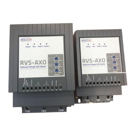
- Page 1 Digital Soft Starter with internal ByPass 3.5-75A, 220 / 400 / 500V Instruction Manual Ver. 0519...
-
Page 2: Table Of Contents
RVS-AXO Instruction Manual TABLE OF CONTENT 2. Safety & Warning ..................3 2.1. Safety .................... 3 2.2. Warnings ..................3 3. Technical Data ................... 4 3.1 Introduction ..................4 3.2 Rating and Frame Sizes ..............4 3.3 Ordering Information ............... 5 4. -
Page 3: Safety & Warning
SAFETY & WARNINGS 2.1 Safety Read this manual carefully before operating the equipment and follow its instructions. Installation, operation and maintenance should be in strict accordance with this manual, national codes and good practice. Installation or operation not performed in strict accordance with these instructions will void manufacturer’s warranty. -
Page 4: Technical Data
3. Technical data Introduction The RVS-AXO is a starter designed for use with standard three-phase, three-wire, squirrel cage, induction motors. It provides the best method of reducing current during motor starting. The RVS-AXO starts the motor by supplying a slowly increasing voltage, providing soft start and smooth acceleration, while drawing the minimum current necessary to start the motor. -
Page 5: Ordering Information
3.3 Ordering Information RVS- 400- 230- Full Mains Control Options Front load Voltage Voltage Panel Current Full load Current Specify Description Starter’s 3, 4.5, 7.5, 11, 15, 22, 30, 37, 45, 60, 75 FLC [A] Mains Voltage Specify Description 220 VAC, 50/60Hz , +10% -15% 400 VAC, 50/60Hz , +10% -15% 500 VAC, 50/60Hz , +10% -15% Control Voltage... -
Page 6: Rvs-Axo Selection
4. RVS-AXO selection. Select RVS-AXO according to motor’s Full Load Ampere (FLA) as indicated on its nameplate (even if the motor will not be fully loaded). RVS-AXO is designed to operate under the following maximum conditions: Starts per hour Ambient Starting current Acceleration temperature ⁰C... -
Page 7: Control Supply (Terminals 1, 2)
Notes: (1) – Circuit breaker provides IEC type 1 coordination. Use fuses for IEC type 2 coordination. Refer to table below. SCR �� ∗ ��(A^2 * sec) Model �� Fuse value RVS-AXO 3 RVS-AXO 4.5 RVS-AXO 7.5 1700 RVS-AXO 11 3630 RVS-AXO 15 6750... -
Page 8: Fault Contact (Terminals 6, 7)
5.5. Fault contact (Terminals 6, 7) It is voltage free, N.O. 5A, 250Vac contact. Contact is closed when soft starter is in Trip state. To reset this state control voltage has to be disconnected and then reconnected. Trip reset can be done via Modbus communication channel as well. 6. -
Page 9: Installation
7. Installation 7.1 Prior to Installation Check that Motor’s Full Load Ampere (FLA) is lower than, or equal, to the starter’s Full Load Current (FLC) and that Mains and Control voltages are as indicated on the starter’s side label. 7.2 Mounting The starter must be mounted vertically. -
Page 10: Operation Interface
8. Operation Interface. 8.1. Control Initial voltage at Start and voltage rise (Start) / reduction time (Stop) set by 3 built-in potentiometers or via Modbus communication channel. - Start / Stop command supplied by external voltage free contact or via Modbus communication channel. -
Page 11: User Interface
8.3. User interface Potentiometers description: Potentiometer Duty Set initial voltage to 30-70%. Set voltage rise time to 1-30Sec. Set voltage reduction time to 0-30Sec. -
Page 12: Protections
LEDs description: duty Power Lights when RVS-AXO energized Blinks at start / soft stop. Lights when bypass is closed. Fault 1 Blinks or lights when RVS-AXO is in fault Fault 2 state. Protections 9.1 Protections list: Active at Factory set Setting range Fault Soft... -
Page 13: Faults Display
9.2 Faults display: Fault LED Fault 1 LED Fault 2 Wrong phase sequence Blinks Phase loss / No voltage Blinks Max Start Time Blinks Blinks Over current Lights Overload Lights Blinks Current unbalance Lights Over Temperature Blinks Lights 9.3 Overload trip time Overload trip delay depends on motor initial state (cold / hot), motor current, selected overload protection grade and selected overload protection pickup. -
Page 14: Setting Parameters
10. Setting parameters. Those parameters can be changed via Modbus communication channel. Parameter Setting range Factory setting Motor FLA 1-100A According to RVS-AO model 0 – by potentiometers Start parameters 1 – by Modbus channel setting 1 – 15 (1 ->30%, 15 ->70%) Initial Voltage Applicable when [Start parameters at Start... -
Page 15: Communication Manual
11. RVS-AXO Instruction Manual TABLE OF CONTENT INTRODUCTION…..............16 2. BASIC STRUCTURE OF THE SERIAL LINK FRAME ....... 17 LIST OF FUNCTIONS SUPPORTED BY THE RVS-AXO ....18 4. ACTUAL DATA (Input registers) ..........19 SETTING PARAMETERS Holding Registers) ........ 21 DISCRETE COMMANDS .............. -
Page 16: Introduction
1. INTRODUCTION This document summarizes the serial link protocol to / from the DIGITAL SOFT STARTER (RVS-AXO). Features: RS485 Hardware. Asynchronous serial link. Half duplex. Format: Modbus RTU Mode (Remote Terminal Unit Mode). - Binary, - Each character includes 11 bits: - 1 start bit - 8 data bits, least significant bit sent first. -
Page 17: Basic Structure Of The Serial Link Frame
2. BASIC STRUCTURE OF THE SERIAL LINK FRAME Modbus RTU frame have the same principal structure for both the "Query" transmission from the Master to the Slave (RVS-AXO) and the Response transmission from the Slave to the Master. "Sync": Silent time of at least 3.5 character (3.5 * 11 bit times). Byte 1: Serial Link No. -
Page 18: List Of Functions Supported By The Rvs-Axo
3. LIST OF FUNCTIONS SUPPORTED BY THE RVS-AXO Function Modbus Name Use in RVS-AXO Read Coil Status Read Discrete Commands status. Read Input Status Read Discrete Inputs status. Read Holding Registers. Read Setting Parameters. Read Input Registers. Read actual data. Force Single Coil. -
Page 19: Actual Data (Input Registers)
4. ACTUAL DATA (Input registers) Actual data includes measured values such as currents and mains frequency. It includes also logic information as well as statistic information. All parameters are word (two bytes) parameters. The protocol supports only Reading of these parameters. Address Register Range / Unit... - Page 20 Faults list: Fault Code-1 Code-2 Over temperature Phase loss/ no voltage Over current Over load Current unbalance Negative phase sequence Example 1: To read input registers at addresses 0…2 (Phase currents I1, I2, I3) of RVS-AXO # 18 the host computer should send following frame: Byte 1: Serial Link No.
-
Page 21: Setting Parameters
5. SETTING PARAMETERS (Holding registers) All parameters are word (two bytes) parameters. The protocol supports Reading with function 3 and modifying these parameters with functions 6, 16. Any one of these parameters must modify with care. Harmful results can occur both to the motor and the RVS-AXO by inadequate settings of some parameters. - Page 22 Voltage rise time at Effective only when 0…15 (1…30Sec) start register @20 set to 1 / Modbus control. Otherwise Voltage reduction 0…15 (0…30Sec) potentiometers position time at stop define start / stop program. 300…500%FLA Current Limit level 340% 0 – potentiometer 0 –...
- Page 23 Example 2: To Read holding registers at addresses 4 and 5 (O/C protection level, delay) of RVS-AXO # 18, the host computer should send following frame: Byte 1: Serial Link No. ($12) Byte 2: Function ($03) Byte 3: Starting Address High ($00) Byte 4: Starting Address Low...
- Page 24 The RVS-AXO normal response, is an echo of the query: Byte 1: Serial Link No. ($12) Byte 2: Function ($06) Byte 3: Starting Address High ($00) Byte 4: Starting Address Low ($04) Byte 5: Preset Data High ($02) Byte 6: Preset Data Low ($58) Byte 7:...
-
Page 25: Discrete Commands
6. DISCRETE COMMANDS (@0…@7 coils) The RVS-AXO incorporates 8 "Coils", (bit parameters). Address Coil Usage 1 – Start, 0 - Stop Start / Stop Reserved Reserved Reserved Reserved Reserved Reserved 1 – Reset. Reset Example 5 - Force Single Coil: To start the motor controlled by RVS-AXO # 18, the host computer should write "1"... - Page 26 DISCRETE HARDWIRED INPUTS Reading The RVS-AXO incorporates 8 Discrete Inputs, (bit parameters). Address Input Usage 1 – Closed, 0 - Open Start / Stop Reserved Reserved Reserved Reserved Reserved Reserved Reserved Example 6: To read Start / stop input status the host computer should send following Query frame: Byte 1: Serial Link No.
-
Page 27: Diagnostics
7. DIAGNOSTICS Modbus Function 08, as implemented in the RVS-AXO supports only Sub-function $0000. It provides for "loopback" (Return Query Data) feature, for checking the Communication Serial Link between the master and the RVS-AXO. To request RVS-AXO # 18 to return Query data, the master should send following Query frame: Byte 1: Serial Link No. - Page 28 EXCEPTION RESPONSES When the master sends a query frame to an RVS-AXO, one of the following four responses from the RVS-AXO is possible: 1. When no communication error is detected in the query, and no mistake is found by the communication program module in the RVS-AXO, a normal response is returned.
- Page 29 Exception Codes supported by the RVS-AXO: Exception Code Type Comment Illegal Function Requested Function is not supported. Functions 1..6, 8, 15 or 16 are supported. Illegal Data Address Data address is not allowable. Illegal Data Value Data Value is not in allowable range. RVS-AXO Busy RVS-AXO is busy now.
- Page 30 Note: There are cases where the RVS-AXO returns Normal response, but the requested action cannot be performed, or is modified by the RVS-AXO. Few examples are: Requested Action Performed Action Writing Setting parameters during start process Ignored. Writing few parameters (Function 16), some are out of range Limiting allowed range.
Need help?
Do you have a question about the RVS-AX0 and is the answer not in the manual?
Questions and answers