
Related Manuals for Solcon HRVS-DN


Summary of Contents for Solcon HRVS-DN
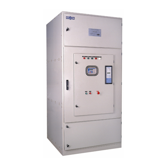
- Page 1 HRVS-DN Medium Voltage Soft Starters 2300 - 13800V, 60-1200A Instruction Manual September 2006...
- Page 2 For further information see Technical Specification Warnings • Internal components and P.C.B’s are at main potential when the HRVS-DN is connected to main voltage. This voltage is extremely dangerous and will cause death or severe injury if contacted. • When HRVS-DN is connected to the main voltage, even if control voltage is disconnected and motors is stopped, full voltage may appear on starter’s output and motor’s...
-
Page 3: Table Of Contents
Table of Contents Page Subject Starter Selection Installation Internal Setting Control Terminals Control Terminals – Option Boards 11-12 Control Wiring Wiring Diagrams Wiring Diagrams Diesel Generator 15-16 Wiring Diagrams – Communication 17-18 Start & Stop Parameters 19-20 Motor And Starter Protection Motor And Starter Protection Occurrence Table Standard wiring Diagram Front Panel... -
Page 4: Starter Selection
System Voltage PIV Ratings torque during motor starting. 2300V 6900V 3300V 12500V The HRVS-DN starts the motor by supplying a slowly 4160V 12500V increasing voltage to the motor, providing soft start and 6600V 19500V smooth acceleration, while drawing the minimum... -
Page 5: Installation
(consult factory). WARNING Power factor correction capacitors, if required must be installed on the line side of the HRVS-DN Do not connect three phase voltage without starting the HRVS-DN for more than 30 seconds. 4 4 4 4... -
Page 6: Internal Setting
Internal Settings Control Module for HRVS-DN is identical for all ratings and suitable for mounting in L.V. Compartment Control Module Connection • Install the module in the L.V. compartment, which should be fully segregated from the H.V. compartment. • Ensure that Control Module is properly grounded. - Page 7 2. Parameters can now be modified from the Built-in memory systems keypad (if starter is in one of the operating The HRVS-DN incorporates 3 memory systems: modes and software lock is open – Dip Switch 8 open). A read-only, non-volatile memory, 3.
- Page 8 Internal Settings Test condition with test harness and four pairs Switch # 2 – Tacho feedback (Optional) of dip - switches allowing a 400V motor test. Set Dip Switch. # 2 to On, when using Incremental Shaft Encoder or tacho feedback. Dip Switch settings (PC2050) Dip Switch The Dip Switch module...
-
Page 9: Control Terminals
By special order it can be supply for 24-110VDC. Dual Adjust / Reset ........Terminal 8 Note: The HRVS-DN is supplied as standard with the Input from a N.O contact. Selection between above same voltage for Control Supply & Control functions is made from the keypad or through the Inputs. - Page 10 Control Terminals Immediate/Shear-pin Relay..Terminals 10-11-12 End of Acceleration Contact..Terminals 16-17-18 Terminals: 10-N.O. 11-N.C. 12 - Common. Terminals: 16 - N.O. 17 - N.C. 18 - Common Voltage free 8A, 250VAC max. Selection between functions is made from the keypad or Voltage free 8A, 250VAC, 2000VA max.
-
Page 11: Control Terminals - Option Boards
Control Terminals – Option Boards RS-485 Communication ....Terminals 23-24 Terminals: 23 (-), 24 (+) and terminal 22 (GND). Optional RS485, half duplex with MODBUS protocol, baud rate 1200, 2400, 4800, 9600 BPS. Twisted shielded pair should be used and shield connects to ground on the PLC/Computer side. -
Page 12: Control Wiring
Control Wiring If External faults are not used leave terminals Control supply 19, 20, 21 open. Firing Supply output A 10A fuse must protect control Supply. N- control supply It is recommended to use a separate fuse for the Stop auxiliary circuits. - Page 13 Control Wiring 1. Motor will soft start when Motors will soft start Motors will soft start closes stop and soft stop with C. and soft stop with C. immediately when act as emergency opens. stop. 12 12 12 12...
-
Page 14: Wiring Diagrams
To incorporate soft stop, use Run contact off delay to “Hold” the Line Contactor. This system is used mainly when the HRVS-DN is retrofitted into an existing system, thus, reducing modifications in existing installations. Main power and Start signal are switched on upon closure of the series contactor. The starter will operate as long as the series contactor is closed. -
Page 15: Wiring Diagrams Diesel Generator
Wiring Diagrams – Diesel Generator FOR STARTING FROM GENERATOR ALWAYS TRY START CURVE 0 FIRST! When starting from a Diesel – Generator, the voltage regulator (especially older type regulators) may be affected during the starting process and cause a rapid voltage fluctuations. In these rare cases, the voltage regulator must be upgraded –... -
Page 16: Wiring Diagrams - Communication
Disconnect control supply, so the new information will be loaded on the next time you turn it on. • Connect a communication line (twisted shield pair) with its (+) to HRVS-DN terminal 24 and (-) to terminal 23, on MODBUS, connect the other end to your host computer containing RS-485 communication port with MODBUS protocol. - Page 17 Wiring Diagrams - Communication Soft-start and immediate stop Soft-start, soft-stop and immediate stop Same as the explanation for soft-start and soft-stop Same as the explanation for Soft-start and soft-stop except # 4: except # 2 and # 4: 4. During operation via communication link, terminals 2.
-
Page 18: Start & Stop Parameters
Range: 10-50% Un (consult factory for extended The HRVS-DN incorporates 5 different starting curves: range). This adjustment also determines the inrush current and Start Curve 0 – Basic curve. Uses less feedback mechanical shock. - Page 19 Pump Control – Stop curve contactor. Load will be transferred to the Intended to prevent water hammer during stopping. HRVS-DN and voltage begins to ramp down. In pump applications, load torque decreases in square relation to the speed and reducing the voltage will...
-
Page 20: Motor And Starter Protection
Motor & Starter Protection Too Many Starts Overload (OL) Inverse time electronic overload Combines three parameters: becomes operational when RUN LED is on. • The OL circuitry incorporates a Number of Starts Thermal Memory Register, which Determines the maximum allowable number of calculates heat less... - Page 21 Motor & Starter Protection Over Voltage By-pass Open Operational after start signal. It trips the starter when Operational when the by-pass contactor did not close main voltage exceeds the Over Voltage Trip set point after End Of Acceleration contact signaled the pilot for an adjustable period of time longer than Over (interposing) relay to close.
- Page 22 Motor & Starter Protection Occurrences Table Active During Timing And Occurrence Start Stop Soft Stop √ Too many starts √ Electronic Overload Shear Pin (Jam) * Default setting √ √ √ Starter Protection – trip function at 850% FLC in less than 1 cycle. Motor Protection –...
-
Page 23: Standard Wiring Diagram
Standard Wiring Diagram Will be send upon request 22 22 22 22... -
Page 24: Front Panel
Front Panel Provides selection of the following LED Arrangement Keypad modes: When Dip Switch 1 is in “On”, gray Lights on when Control Supply voltage is connected to zone shows list of maximized Mode the starter. parameters). • Start Display Only •... -
Page 25: Display Mode
Press Store and Mode keys simultaneously. PARAMETERS CAUTION START PARAMETERS Obtaining Default Parameters will erase all previously modified settings. STOP PARAMETERS HRVS-DN FLC must be set to the rated starter current DUAL ADJUSTMENT as specified on the starter label. PARAMETERS FAULT PARAMETERS I/O PROGRAMMING PARAMETERS COMM. -
Page 26: Parameter Settings
Parameter Settings Press Mode Press Select Press Select To advance to: Press keys to set Overload Press keys to set Over Trip time delay at 500% of motor Voltage Trip. MAIN & PROTECT. FLA. Range: 110-125% of Un (can not PARAMETERS Range: 1-10 sec. - Page 27 Parameter Settings Press Select , Press Mode To Advance to: Press keys to set Current Limit Range: 100-400% of motor FLA. START PARAMETERS CURRENT LIMIT 400% OF FLA Press Select Press Select SOFT START CURVE Press keys to set Acceleration Time 1 (STANDARD) Range: 1-30 sec.
- Page 28 Parameter Settings Press Mode Press Mode To advance to To advance to Dual Adjustments when Dip Switch # 1 is set to ON: STOP PARAMATERS DUAL ADJUSTMENT PARAMETERS Press Select When selecting “Generator Mode” (Dip sw # 3 is On) the Then press keys to set Soft Stop Curve following display appears instead of the above.
- Page 29 Parameter Settings Press Mode Press Select Set Dip Switch # 1 to ON to advance to: Then press keys to enable or disable “SET CURVE 0 FLT”. FAULT PARAMETERS Range: Enable\ Disable. Set to disable, only if “SET CURVE TO 0” fault occurs during starting and if curve 0 starting process is not good Press Select enough for the application.
- Page 30 Parameter Settings Press Mode Press Mode Set Dip Switch # 1 to ON, to Advance to: Set Dip Switch # 1 to ON, to Advance to: I/O PROGRAMMING COMM. PARAMETERS PARAMETERS Communication is optional and operates only when Press Select starter incorporates this feature.
- Page 31 Parameter Settings Press Select Then press keys to set the protocol: Press Select Then press keys to set Communication Serial Link COMM. PROTOCOL Number PROFIBUS Range: 1-127 (for up to 32 starters on one twisted pair) For MODBUS parameters see page 29. SERIAL LINK NO.
- Page 32 Parameter Settings Press Mode To advance to Press Mode to return to Display Mode STATISTICAL DATA -****- Note: It is possible to scroll with the arrow buttons. Service Mode Press Select Press Mode and simultaneously. The LCD LAST STRT PERIOD displays: NO DATA Displays last starting time in seconds.
-
Page 33: Start-Up Procedure
Limit”. The voltage is held at this value until motor is close Current Limit setting. to nominal speed, then current will begin to decrease. The HRVS-DN continues to ramp-up the voltage until reaching Press Stop and wait until motor stops. nominal. Motor speed smoothly accelerates to full speed. -
Page 34: Menu Description
Menu Description MODE MODE MODE MODE MODE UPON INITIATION PAGE 1 PAGE 2 PAGE 3 PAGE 4 PARAMETERS DISPLAY MAIN & PROTECT. DUAL ADJUSTMENT START PARAMETERS STOP PARAMETERS PARAMETERS PARAMETERS SELECT SELECT SELECT SELECT SELECT PRESS KEYS TO CHANGE PARAMETER VALUE STARTER FLC SOFT START CURVE SOFT STOP CURVE... - Page 35 Menu Description MODE MODE MODE MODE MODE PAGE 5 PAGE 6 PAGE 7 PAGE 9 PAGE 8 I/0 PROGRAMING STATISTICAL DATA - FIRING TEST FAULT PARAMETERS COMM. PARAMETERS PARAMETERS DISCONNECT MAINS SELECT SELECT SELECT SELECT SELECT PRESS KEYS TO CHANGE PARAMETER VALUE Not Applicable Note: Program input # 7 to test...
- Page 36 Menu Description STORE ENABLE PROGRAM VERSION SELECT RESET STATISTICS SELECT MODE DEFAULT PARAMET. MVSTRT .DN-311298 MODE + STORE RESET + STORE SELECT VOLTAGE ADJUST. SAVE DEFAULT 1% OF Un PARAMETERS & SAVE STATISTICAL BACK TO DATA & BACK TO PARAMETERS PAGE 9 CURRENT ADJUST.
-
Page 37: Trouble Shooting
PWR ON & NO the HRVS-DN for more than 30 seconds without a start signal. START It operates when the by-pass contactor did not close after EOA contact of the HRVS-DN BY-PASS OPEN closes. Note: This protection can be disable by setting By Pass open trip to disable when the By Pass is connected in a separate in a separate cabinet such that the starter CT’s do not... - Page 38 Trouble Shooting PHASE LOSS Trips the starter if 1 or 2 phases are missing. Check lines voltages and correct connection (see page 4). PHASE Trips the starter if line phase sequence is wrong. Check line phase sequence. If wrong, swap SEQUENCE two wires on line side.
-
Page 39: Technical Specification
Technical Specification General Information: Supply Voltage ........Line to Line 2,300V, 3,300V, 4,160V, 6,000V, 6,600V, 6,900V, 11,000V, 13,800V (other voltages TBD) + 10%-15% P.I.V ratings ........For 2,300V PIV is 6,900V; For 3,300V PIV is 12,500V; For 4,160V PIV is 12,500V;... - Page 40 Technical Specification Control: Displays ..........LCD in 4 – Field selectable languages and 8 LEDs Keypad ..........6 keys for easy setting Aux. Contact – Immediate ....1 C/O, 8A, 250VAC, 2000VA Aux. Contact – End of Acceleration ..1 C/O, 8A, 250VAC, 2000VA Fault Contact ........1 C/O, 8A, 250VAC, 2000VA Communication........RS 485 with MODBUS or PROFIBUS protocols Temperatures ........Operating -10˚...
Need help?
Do you have a question about the HRVS-DN and is the answer not in the manual?
Questions and answers