Table of Contents
Advertisement
Advertisement
Table of Contents

Related Manuals for Solcon RVS-DN


Summary of Contents for Solcon RVS-DN
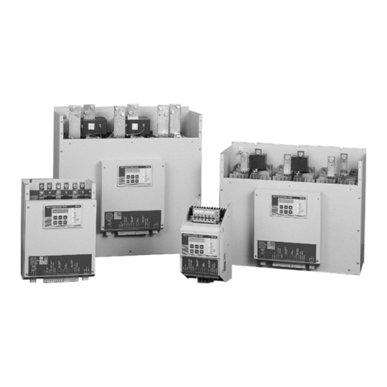
- Page 1 RVS-DN Digital Soft Starter 8-3500A, 220-1000V Instruction Manual Ver. 12/10/2003...
-
Page 2: Table Of Contents
• This product was designed for compliance with IEC 947-4-2 for class A equipment. • RVS-DN 8 - 820 are UL approved. RVS-DN 950 - 3500 are designed to meet UL requirements. • RVS-DN 8 - 1400 are LR approved. RVS-DN 1800 - 3500 are designed to meet LR requirements. -
Page 3: Starter Selection
Select the starter according to motor’s Full Load Ampere (FLA) – as indicated on its nameplate (even if The RVS-DN starts the motor by supplying a slowly the motor is not fully loaded). increasing voltage to the motor, providing soft start and... -
Page 4: Installation
RVS-DN itself. Any such connection may cause damage to the load which was connected to it or to the RVS-DN itself! -
Page 5: By-Pass Contactor
U L1 V L2 W L3 which by passes the RVS-DN after completion of start- mounted on line side, up, so motor current will flow through the by-pass after the C/T’s marked contactor. . Bypass... -
Page 6: Control Terminals
Automatic mode may be used only if by-pass communication (see I/O Programm.) contactor is directly controlled by the RVS-DN “End- of-Acceleration” contact. • When Energy Save function is selected –connect terminal 7 to control voltage by a jumper for automatic operation, upon load decrease. - Page 7 Control Terminals Dual Adjust Reverse / Reset Terminal 8 Immediate/Shear-pin Relay Terminals 10-11-12 Input from a N.O contact. Selection between above Terminals: 10- N.O. 11-N.C. 12 – common. functions is made from the keypad or through the Voltage free 8A, 250VAC, 2000VA max. communication (see I/O Programming ).
- Page 8 Control Terminals Fault Contact Terminals 13-14-15 Tacho Feedback – Optional Terminal 20 Terminals: 13-N.O. 14-N.C. 15 – Common. Provides linear acceleration and deceleration. Requires high quality Tacho generator on motor shaft, Voltage free 8A, 250VAC, 2000VA max. changes its output voltage 0-10VDC, linear speed/voltage ratio. position on fault.
-
Page 9: Control Terminals - Option Boards
No use No use * Default Notes: 1. It is important that the RVS-DN is properly grounded, and control module is tightly fastened to the power section. 2. Option # 5 and option # 4 may not be applied together. -
Page 10: Control Wiring
Control Wiring Internal Jumper-see page 13 Fusing – Control Supply must be protected by a 6A fuse. It is recommended to use a separate fuse for the auxiliary circuits. Control Supply Stop Control Supply and Control Inputs Soft Stop from the same source, Neutral Start connected to Terminal 21. -
Page 11: Wiring Diagrams
Wiring Diagrams 1. Start, soft stop and stop 2. Start-Stop push buttons, single supply buttons, Separate source for Control Supply sources for Control and Control Inputs. Supply and Control Stop Stop If Soft Stop is not used, Inputs. Soft Stop Soft Stop connect a jumper between If Soft Stop is not... - Page 12 1 2 3 4 5 6 7 8 9 10 11 12 13 14 15 16 17 18 19 20 U V W This system is mainly used when the RVS-DN is End of Acceleration contact is activated after an retrofitted into an existing system, to reduce adjustable time delays “Run Contact Delay”...
- Page 13 * Motor FLA. An additional N.O. contact (15-16) on the high-speed contactor should act as the Dual Adjustment Switch. It should close simultaneously with 13-14 of the same contactor to start the RVS-DN and to switch to the Dual Adjustment settings.
-
Page 14: Wiring Diagrams - Communication
Disconnect control supply, so the new information will be loaded on the next time you turn it on. • Connect a communication line (twisted shielded pair) with its (+) to RVS-DN terminal 24 and (-) to terminal 23, connect the other end to your computer containing RS-485 communication port with MODBUS protocol. - Page 15 Wiring Diagrams - Communication Operation communication link with Operation via communication link with Momentary Local/Remote (selector switch) contact (Push-Buttons) Soft-start, immediate stop, • soft-stop. Remote: via Communication link • Local: Soft-start, immediate-stop by maintaining contact. 3 4 5 6 Start Soft Stop Remote Local Immediate...
-
Page 16: Wiring Diagrams - Diesel Generator
Wiring Diagrams – Diesel Generator Starting from Diesel-Generator Line Bypass Contactor Contactor L1 L2 Dip. Sw. S1 End Of Acceleration 1 2 3 4 5 6 7 8 9 10 11 12 13 14 15 16 17 18 19 20 21 U V W Start Stop... -
Page 17: Wiring Diagrams - Brake Motor
Wiring Diagrams – Brake Motor & Insulation Test Brake Motor Insulation Test Wiring Control supply before C1 Control supply before C1 L1 L2 L1 L2 Insulation Alarm Immediate Contact 1 2 3 4 5 6 7 8 9 10 11 12 13 14 15 16 17 18 19 20 1 2 3 4 5 6 7 8 9 10 11 12 13 14 15 16 17 18 19 20 Few conditions must exist for the Insulation circuitry to Upon starting, the “Immediate”... -
Page 18: Internal Setting
Communication Fan Control Jumper Board Fan Control Built-in memory systems Starter’s fan(s) can be The RVS-DN incorporates 3 memory systems: Internal Jumper controlled by in internal jumper. It is recommended EPROM A read-only, non-volatile memory, continuous containing factory set parameters (default) that cannot Relay operation as default. - Page 19 Inside Delta Motor Connection Mode Switch # 2 – Tacho feedback (0-10VDC) Allows connection of the RVS-DN inside the Delta. Set Dip Sw. # 2 to On, when using Tacho feedback. Current is reduced by 1.73 (√3), namely for an 800A motor the standard selection will be an 820A soft- Note: To operate tacho feedback –...
-
Page 20: Start And Stop Parameters
This adjustment also determines the inrush current and mechanical shock. A setting that is too high The RVS-DN incorporates 4 different starting curves: may cause high initial mechanical shock and high Start Curve 0 – Standard curve (Default). The most... - Page 21 Start & Stop Parameters Note: When the starter operates with a by-pass Maximum Start Time The maximum allowable starts time, from start signal contactor, Soft Stop initiation opens the End Of to end of acceleration. If voltage does not reach full Acceleration contact, tripping open the by-pass voltage during this time (for example, because of low contactor.
-
Page 22: Motor And Starter Protection
Motor & Starter Protection Motor Insulation (option) Over Current Shear-pin Operational when motor is not running (the motor must Becomes operational when starter is energized and has be galvanically isolated). Two distinct level can be set two Trip functions: for Alarm and Trip functions. •... - Page 23 Motor & Starter Protection Over Voltage Heatsink Over Temperature Becomes operational only after start signal. Trips the Thermal sensors are mounted on the heatsink and trip starter when main voltage increases above the set Over the starter when temperature rises above 85ºC. Voltage Trip (OVT) Level for an adjustable period of time longer than Over Voltage Delay (OVD).
- Page 24 Front Panel Provides selection of the following LED's Arrangement Keypad modes: (When Dip Switch 1 is in “On”, gray Lights up when Control Supply voltage is connected to zone shows list of maximized starter. parameters). Start • Display Only Lights up during start process, indicating that motor •...
- Page 25 Front Panel LCD Arrangement Mode pages Two lines of 16 alphanumeric characters, displaying: Upon initiation of the starter, the LCD displays motor’s System Parameters, Starter Settings, Motor Current, operating current. Insulation and Fault Identification. Four selectable languages – English, French, German % OF MOTOR FLA and Spanish (see Dip Switch setting –...
- Page 26 Display Mode In this mode, parameters cannot be adjusted Press Select % OF MOTOR FLA ANALOGUE OUTPUT Normal Displays operating current as a percentage of motor FLA. Normal- Analogue output increases when Note: Starter’s Default Display, after pressing current increases. Mode or Select, a time delay is initiated.
-
Page 27: Parameter Setting
LINE / INSIDE DELTA Range: 120-600V UNDERVOLT. TRIP Press Select 300 VOLT ▲▼ Press keys to set Starter’s FLC. (see RVS-DN ratings – Page 3). Press Select ▲▼ STARTER FLC Press keys to set Under Voltage Trip Delay 105 AMP Range: 1-10 sec. - Page 28 Parameter Settings Range: 100-400% of motor FLA. Press Mode To Advance to: CURRENT LIMIT 400% OF FLA START PARAMETERS Press Select Press Select ▲▼ Press keys to set Acceleration Time SOFT START CURVE Range: 1-30 sec. 0 (STANDARD) ACC. TIME ▲▼...
- Page 29 Parameter Settings Press Mode Press Mode To advance to To advance to (only when Dip Sw. # 1 is set to ON): STOP PARAMATERS DUAL ADJUSTMENT PARAMETERS Press Select When selecting “Generator Mode” (Dip sw # 3 is On) ▲▼ the following display appears instead of the above.
- Page 30 Parameter Settings Press Mode Press Mode Set Dip. Sw. # 1 ON, to advance to: Set Dip. Sw. # 1 ON, to advance to: Energy Save and Slow Speed Modes FAULT PARAMETERS EN. SAVE & SL. SPD PARAMETERS Press Select ▲▼...
- Page 31 Parameter Settings Press Mode Press Mode Set Dip Sw. # 1 ON, to Advance to: Set Dip Sw. # 1 ON, to Advance to: I/O PROGRAMMING COMM. PARAMETERS PARAMETERS Communication is optional and operates only when Press Select starter incorporates this feature. ▲▼...
- Page 32 Parameter Settings Press Mode Service Mode To Advance to Press Mode and keys simultaneously, the LCD STATISTICAL DATA displays: **** STORE ENABLE DEFAULT PARAMET. Press Select To store selected parameters, press Store key Press Store and Mode simultaneously to store factory LAST STRT PERIOD Default Parameters.
- Page 33 11. If acceleration time is too short, increase until motor is close to nominal speed, then current will “Acceleration Time” setting. begin to decrease. The RVS-DN continues to ramp-up 12. Check total starting time and set Max. Start the voltage until reaching nominal. Motor speed Time to approx.
- Page 34 Pump Control Choosing a suitable Pump Curve (centrifugal Pumps) Starting Curve 1. Adjust main parameters as necessary (FLA, FLC, etc..) Set Starting Curve, Acceleration Time, Current Limit, and Initial Voltage to their default values (curve 0, 10 sec., 400% and 30% respectively).
-
Page 35: Menu Description
Menu Description MODE MODE MODE MODE MODE UPON INITIATION PAGE 1 PAGE 2 PAGE 3 PAGE 4 PARAMETERS DISPLY START STOP DUAL ADJUSTMENT % OF MOTOR FLA MAIN PARAMETERS PARAMETERS PARAMETERS PARAMETERS SELECT SELECT SELECT SELECT SELECT TO REVIEW ALL PRESS KEYS TO CHANGE PARAMETER VALUE PARAMETERS... - Page 36 Menu Description MODE MODE MODE MODE MODE PAGE 5 PAGE 6 PAGE 7 PAGE 8 PAGE 9 EN. SAVE & SL. SPD FAULT I/0 PROGRAMING COMM. STATISTICAL DATA PARAMETERS PARAMETERS PARAMETERS PARAMETERS -****- SELECT SELECT SELECT SELECT SELECT PRESS KEYS TO CHANGE PARAMETER VALUE SAVING ADJUST PHASE SEQ Y/N...
-
Page 37: Trouble Shooting
Trouble Shooting Upon fault – motor stops, Fault LED lights and Fault Relay operates. The LCD shows TRIP: and fault description. Upon Alarm – motor continues running, Alarm Relay operates and Fault LED flashes. The LCD shows ALARM: and fault description (for example: ALARM: MOTOR INSULATION). - Page 38 Trouble Shooting UNDER VOLTAGE Trips the starter when line voltage drops below the preset level for the preset time. Check “Under Voltage Trip “ and “Time Delay” settings, check line voltages on L . When voltage drops to zero, the starter trips immediately with no delay. OVER VOLTAGE Trips the starter when line voltage increases above a preset level for a preset time.
-
Page 39: Technical Specification
Technical Specification General Information: Supply Voltage ........Line to Line 220-690V (to be specified) + 10%-15% Frequency ..........45 – 65 Hz (Fixed or variable frequency source) Control Supply ........110-230V (to be specified) +10% - 15% Control inputs & Outputs ....Either same as Control Supply or by special order 24-230V AC/DC (to be specified) Load............. - Page 40 Technical Specification Control: Displays ..........LCD in 4 – Field selectable languages and 8 LEDs. Keypad..........6 keys for easy setting Aux Contact – Immediate....1 C/O, 8A, 250VAC, 2000VA Aux Contact – End Of Acceleration..1 C/O, 8A, 250VAC, 2000VA Fault Contact ........
-
Page 41: Fuse Selection
Appendix Table of Contents Page Subject UL and cUL installation instructions, LR recommendations Fuse selection (A Motor and starter Timing Occurrence Table Warranty Report and Problem Inquiry “Inside Delta” Description Overload Trip Time (Approximate calculation) 46-50 Dimensions and Weights Block Diagram and Notes Ordering Information... - Page 42 UL, cUL Installation Instructions LR Recommendation 1. Input power and output motor field wiring LR recommendations for marine, offshore or industrial shall be copper conductors, rated 75ºC. use. 2. Use UL listed closed-loop connectors sized for the selected wire gauge. Install connectors System design needs to take into account the power using the correct crimp tool recommended by supply source and the motor drive together with the...
- Page 43 Fuse Selection (Recommended Values For Main Supply Of 400V) RVS-DN Max. thyristor I BUSSMAN Schneider GEC ALSTOM JEAN MULLER FERRAZ - SHAUMAT FERRAZ publication Fuse Value Allowed (A Sec) Ultra Fast Fuse Semicon Fuse Reference / Publication RVS – DN 8 T.B.D.
- Page 44 Motor and Starter Protection Occurance Table Active During Timing And Occurrence Soft Start Stop Stop √ Too many starts with Start Inhibit period √ Electronic Overload with Curve selection Shear Pin (Jam) * Default setting √ √ √ Starter Protection – trip function at 850% FLC Motor Protection –...
- Page 45 Example: 390 – 400 – 230 – 230 – 3 + 4 + 9 + L + A + B – S Options: RVS-DN _ _ _ _ - _ _ _ - _ _ _ - _ _ _ - _ + _ + _ + _ + _ - _ Serial Number:...
- Page 46 Inside Delta, at 400V Starter Type Soft-Starter Motor KW @400V Motor KW @ 400V In Line Current (A) “In- Line” “Inside Delta” RVS-DN 8 RVS-DN 17 RVS-DN 31 RVS-DN 44 RVS-DN 58 RVS-DN 72 RVS-DN 85 RVS-DN 105 RVS-DN 145...
- Page 47 Overload Trip Time Calculation Note: In overload procedure, current is limited to 5 x Motor FLA to prevent saturation in calculation, so trip time at 5 or 8 times motor FLA will be identical. The approximate trip time is given in the following equation: ×...
- Page 48 Dimensions (mm) FRAME SIZE - A 8,17A 44, 58, 72A L1,L2,L3 L1,L2,L3 L1,L2,L3 U,V ,W U,V,W U,V,W Note: Main voltage terminals size: 8A – 58A - 16mm - 25mm...
- Page 49 Dimensions (mm) FRAME SIZE – B (Standard) 105, 145, 170A With preparation for by-pass contactor Drawing will be delivered upon request Drawing will be delivered upon request FRAME SIZE – B (New – New type includes preparation for bypass as standard 85, 105, 145, 170A (Deep Type) 8 .
- Page 50 FA N FA N FA N 187.5 187.5 RVS-DN • The starter can be supplied with line & load bus-bars at the bottom • The starter can be supplied without side covers, with max width of 536 mm (instead 590) 187.5...
- Page 51 Dimensions (mm) FRAME SIZE - D 460, 580, 820A 150.5 12.5 12.5 67.5 1 0״ • The starter can be supplied with line & load bus-bars at the bottom Preparation for by-pass contactor 150.5 73.5 12.5 12.5 1 0״...
- Page 52 1 4״ Starter Current FLC Frame Weight Width Height Depth Type (Amp) Size (Kg.) RVS-DN 8, 17 44, 58, 72 105, 145, 170 15.1 210, 310, 390 44.8 460, 580, 820 1100, 1400, 1800 1100 2150 1300 2400, 2700, 3000,...
- Page 53 RVS DN Block Diagram Block Diagram for the RVS-DN control, power and firing module, inputs and option boards. Power Isolated Keypad supply Inputs I Measurements Preparation display for by pass MICRO All protection PROCESSOR Firing circuitry SCRs remain active display...
-
Page 54: Ordering Information
Specify Standard Notes: (a) RVS-DN ratings 1100-3500 have to be used with a by-pass. (b) RVS-DN size A (8-72A), options should be factory supplied. (b) Only one option, either #4, # 5 or # T may be installed in one starter.
Need help?
Do you have a question about the RVS-DN and is the answer not in the manual?
Questions and answers