
Summary of Contents for Ecolink Z-Wave TBZ500
- Page 1 ® Z-Wave Thermostat TBZ500 Battery Powered Z-Wave Thermostat Installation & Operation Guide Copyright © Ecolink Intelligent Technology TBZ500_manual_8_5x5_5_inch Combined_RDN1240221.indd 1 24-02-2021 18:55...
- Page 2 Copyright © Ecolink Intelligent Technology TBZ500_manual_8_5x5_5_inch Combined_RDN1240221.indd 2 24-02-2021 18:55...
-
Page 3: Table Of Contents
Menu Mode Navigation ......14 Limited Warranty ............27 System Setup Menu ........14 Advanced Systems Settings Menu ......... 15 Return Policy ............... 27 Settings Menu Table ....... 15 – 17 Copyright © Ecolink Intelligent Technology TBZ500_manual_8_5x5_5_inch Combined_RDN1240221.indd 3 24-02-2021 18:55... -
Page 4: Thermostat Features
Installation Outline • Step 1 Remove Existing Thermostat • Step 2 Install TBZ500 Thermostat • Step 3 Setup Thermostat to match System Type • Step 4 Install into Z-Wave Network Copyright © Ecolink Intelligent Technology TBZ500_manual_8_5x5_5_inch Combined_RDN1240221.indd 4 24-02-2021 18:55... -
Page 5: Thermostat Compatible Hvac Systems
Note! If the thermostat is powered from 24VAC, do not install batteries! Z-Wave Operation when 24VAC powered If the thermostat is installed on a Z-Wave network while it is 24VAC powered, it operates as an always-on Z-Wave repeater. Copyright © Ecolink Intelligent Technology TBZ500_manual_8_5x5_5_inch Combined_RDN1240221.indd 5 24-02-2021 18:55... -
Page 6: Installation Steps
When the wire is absent, the thermostat must be powered by batteries. such as Y2, W2. If you have RC and/or RH connections, see below. Other wires are not used. Copyright © Ecolink Intelligent Technology TBZ500_manual_8_5x5_5_inch Combined_RDN1240221.indd 6 24-02-2021 18:55... -
Page 7: Wiring Colors
Connect the wires as marked from the HVAC system to the corresponding terminals on the thermostat back. *C wire (24VAC common) may not be present. If not, batteries must be installed. Copyright © Ecolink Intelligent Technology TBZ500_manual_8_5x5_5_inch Combined_RDN1240221.indd 7 24-02-2021 18:55... -
Page 8: Separate Transformer Hvac System
Heating R to RH and • 1 Stage heating Cooling R to RC. NOTE! REMOVE THE FACTORY • 1 Stage cooling INSTALLED RC/RH JUMPER. No Setup change required for this configuration Copyright © Ecolink Intelligent Technology TBZ500_manual_8_5x5_5_inch Combined_RDN1240221.indd 8 24-02-2021 18:55... -
Page 9: Single And Dual Transformer Systems (Split Systems)
Connect to W1 terminal Connect to W2 terminal (2-stage system only) IMPORTANT!: for separate rc/rh systems, the internal rc=rh jumper must be cut on the back of the thermostat’s printed circuit board. Copyright © Ecolink Intelligent Technology TBZ500_manual_8_5x5_5_inch Combined_RDN1240221.indd 9... -
Page 10: Heat Pump Hvac System Wiring
Heat) in the SETUP menu. the RC or RH terminal. Connect the R wire to either RC or DO NOT REMOVE THE RH terminal. RC/RH JUMPER Factory installed RC/RH jumper Copyright © Ecolink Intelligent Technology TBZ500_manual_8_5x5_5_inch Combined_RDN1240221.indd 10 24-02-2021 18:55... -
Page 11: Thermostat Setup: Heat Pump Hvac Systems
2nd stage cool enable: Enable second stage cooling outputs If a single stage cooling system, leave this set to N. If a two stage cooling system, set to Y to enable. Copyright © Ecolink Intelligent Technology TBZ500_manual_8_5x5_5_inch Combined_RDN1240221.indd 11 24-02-2021 18:55... -
Page 12: Mount The Thermostat
After all connections are made and thermostat us mounted, turn on power to the HVAC system/thermostat by either re-energizing the circuit breaker in the breaker panel or by plugging in the HVAC system back in to the 120VAC wall outlet. Install batteries Watch polarity! Copyright © Ecolink Intelligent Technology TBZ500_manual_8_5x5_5_inch Combined_RDN1240221.indd 12 24-02-2021 18:55... -
Page 13: Thermostat Setup: Configure For Hvac System
Press and hold the FAN button to enter the Menu Mode. SETUP is the first menu item displayed. Press the down button to advance to the SYSTEM screen. Copyright © Ecolink Intelligent Technology TBZ500_manual_8_5x5_5_inch Combined_RDN1240221.indd 13... -
Page 14: Thermostat Menu Screen
To change the HVAC system default settings, use the down expected or vice versa, change the arrow to progress to the SYSTEM menu item and press “Change Over Type” to the opposite “Select”. setting. Copyright © Ecolink Intelligent Technology TBZ500_manual_8_5x5_5_inch Combined_RDN1240221.indd 14 24-02-2021 18:55... -
Page 15: Advanced Systems Settings Menu
Enables the second stage cool operation Y or N Enable Minimum run Sets the Minimum Run Time (MRT) delay before a heating/cooling cycle can turn time off.Sets heating/cooling cycle time. Prevents rapid on/off cycling. Copyright © Ecolink Intelligent Technology TBZ500_manual_8_5x5_5_inch Combined_RDN1240221.indd 15 24-02-2021 18:55... - Page 16 Stage 3 turns off at setpoint + Delta Stage 3 degrees Cooling Stage 1 Sets the delta from setpoint that stage 1 cooling starts. 1 to 7 On Threshold degrees Copyright © Ecolink Intelligent Technology TBZ500_manual_8_5x5_5_inch Combined_RDN1240221.indd 16 24-02-2021 18:55...
- Page 17 Release the buttons when RESET appears on the Status Line. Once the TBZ500 resets the Z-Wave and HVAC settings, a DONE confirmation message will appear on the screen before the thermostat self-reboots. Copyright © Ecolink Intelligent Technology TBZ500_manual_8_5x5_5_inch Combined_RDN1240221.indd 17...
-
Page 18: Z-Wave Installation
“SUCCESS” will be display when the thermostat has been excluded from the network. Press “Done” to exit back to the thermostat screen. Thermostat is now ready to be added to any Z-Wave network. Copyright © Ecolink Intelligent Technology TBZ500_manual_8_5x5_5_inch Combined_RDN1240221.indd 18... -
Page 19: Operation Instructions
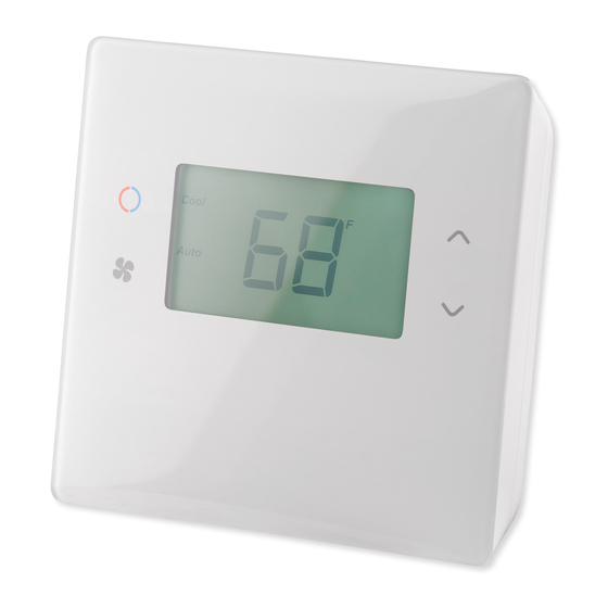
Low Battery indicator For Heat Pump systems only: Display Lock indicator • “Heat-E” = Emergency heat mode active Z-Wave Network Installed indicator Fan Mode indicators System Mode indicators TBZ500 Display Copyright © Ecolink Intelligent Technology TBZ500_manual_8_5x5_5_inch Combined_RDN1240221.indd 19 24-02-2021 18:55... -
Page 20: Setting The System Mode
Caution! Emergency Heat should only be used for emergencies until the HVAC system can be repaired. Running the system in Emergency Heat mode is commonly the most expensive mode since only the electric heat strips are being used instead of the more efficient heat pump compressor. Copyright © Ecolink Intelligent Technology TBZ500_manual_8_5x5_5_inch Combined_RDN1240221.indd 20... -
Page 21: Setting The Heating Or Cooling Temperature Setpoint
1 degree. Press to automatically time out. and hold the button to ramp the setpoint. Copyright © Ecolink Intelligent Technology TBZ500_manual_8_5x5_5_inch Combined_RDN1240221.indd 21 24-02-2021 18:55... -
Page 22: Setting The Fan Mode
Press and hold the FAN button for 5 seconds to go to Press “Done” to go back to the the Menu Mode screen Thermostat Main Screen Use the UP/DOWN buttons to select the desired menu item Copyright © Ecolink Intelligent Technology TBZ500_manual_8_5x5_5_inch Combined_RDN1240221.indd 22 24-02-2021 18:55... -
Page 23: Thermostat Setup Menu
The INFO menu displays information about the thermostat. Use the Up/Dn buttons to scroll through the Change Over valve (reversing valve) various items. setting • AC or Battery Powered: AC POWER will be displayed if power by 24VAC Copyright © Ecolink Intelligent Technology TBZ500_manual_8_5x5_5_inch Combined_RDN1240221.indd 23 24-02-2021 18:55... -
Page 24: Thermostat Operation
Caution! Once installed in a Z-Wave network, if you change how the thermostat is powered (from batteries to 24VAC or vice versa), you must remove and re-enroll the thermostat in the Z-Wave network for it to work correctly. Copyright © Ecolink Intelligent Technology TBZ500_manual_8_5x5_5_inch Combined_RDN1240221.indd 24... -
Page 25: Adding The Thermostat To A Z-Wave Network
“SUCCESS” will be display when the thermostat has been excluded from the network. Press “Done” to exit back to the thermostat screen. Thermostat is now ready to be added to any Z-Wave network. Copyright © Ecolink Intelligent Technology 24-02-2021 18:55 TBZ500_manual_8_5x5_5_inch Combined_RDN1240221.indd 25... -
Page 26: Z-Wave Command Classes
- V5 • COMMAND_CLASS_THERMOSTAT_FAN_MODE COMMAND_CLASS_THERMOSTAT_FAN_STATE • • COMMAND_CLASS_THERMOSTAT_MODE_V3 - V3 • COMMAND_CLASS_THERMOSTAT_OPERATING_STATE_V2 - V2 CCOMMAND_CLASS_THERMOSTAT_SETPOINT_V2/V3 • - V3 • COMMAND_CLASS_VERSION_V2 • COMMAND_CLASS_SECURITY_2 • COMMAND_CLASS_TRANSPORT_SERVICE_V2 • COMMAND_CLASS_SUPERVISION COMMAND_CLASS_CONFIGURATION_V2 • - V2 Copyright © Ecolink Intelligent Technology TBZ500_manual_8_5x5_5_inch Combined_RDN1240221.indd 26 24-02-2021 18:55... -
Page 27: Compliance Statement
Association groups The TBZ500 supports 3 groups and 5 associations per group. Group 1 Association Alerts are to notify an associated device of a thermostat generated change. Thermostat generated changes are those changes that originate at or by the thermostat. The general classifications of thermostat generated changes are: •... - Page 28 Z-Wave Configurations There are configuration parameters accessible via the COMMAND_CLASS_CONFIGURATION. Note all temperature related parameters are in degrees F. Config Length Send Default Parameter Description (bytes) Unsolicited Value Read values Write values on change System Type 4 0 = Standard 1 = Heat Pump 0 = Standard 1 = Heat Pump Fan Type 4 0 = Gas (No fan w/Heat) 1 =...
- Page 29 Default Config Send Length Description Value Read values Write values (bytes) Parameter Unsolicited on change C Delta Stage 1 OFF C Delta Stage 2 ON C Delta Stage 2 OFF Mechanical Status 3 MECH_H1 0x0001 MECH_H2 0x0002 0x15 MECH_H3 0x0004 MECH_C1 0x0008 MECH_C2 0x0010 PHANTOM_F 0x0020...
- Page 30 Config Length Send Default Parameter # Description (bytes) Unsolicited on Value Read values Write values change Backlight Timer 10-30 10-30 Max Heat Setpoint 30F – 109F 30F – 109F Min Cool Setpoint 33F – 112F 33F – 112F Schedule Enable 0 = Disabled 0 = Disabled 1 = Enabled...
- Page 31 Config Length Send Default Parameter # Description (bytes) Unsolicited on Value Read values Write values change UI Wakeup count 0-0x7FFFFFFF 0-0x7FFFFFFF 0xb0 Reserved Power Status POWER_BATTERY 0x01 POWER_24VAC 0xb2 Bits are set according to power setup. 0x02 PWR_ACINSTALL 0x10 PWR_BATINSTALL 0x20 PWR_FLIRS 0x40 Battery Bank Voltage (%)
- Page 32 6 The battery alert enable only applies to the periodic battery report (config reg 185) and not the built in battery threshold alerts (config regs 183, 184) 7 Schedule Enable (#38) must be enabled prior to setting this parameter Copyright © Ecolink Intelligent Technology TBZ500_manual_8_5x5_5_inch Combined_RDN1240221.indd 28...
-
Page 33: Limited Warranty
Ecolink. cause harmful interference to radio communications. However,... - Page 34 Copyright © Ecolink Intelligent Technology TBZ500_manual_8_5x5_5_inch Combined_RDN1240221.indd 28 24-02-2021 18:55...
Need help?
Do you have a question about the Z-Wave TBZ500 and is the answer not in the manual?
Questions and answers
The echolink will not sustain the selected temp
The Ecolink TBZ500 may not be sustaining the selected temperature due to the thermostat enforcing a 3-degree separation between heating and cooling setpoints. If the cooling setpoint is set below the heating setpoint, the thermostat automatically adjusts the heating setpoint lower, and vice versa. Additionally, any change to a mechanical system setting may cause the current HVAC operation to abort and start a new mode of operation (MOT), which may delay temperature regulation. Also, changes to MOT/MRT settings only take effect in the next cycle, which can impact temperature control.
This answer is automatically generated
Something changed with my heating and it's just running. I'm not sure what stage 1,2 and 3 mean but it changes around from those three and I've never noticed those small numbers before. Not sure how to get it back to working the way it was.
To reset the Ecolink Z-Wave TBZ500 thermostat to its original settings (both Z-Wave and HVAC settings):
1. Remove power from the TBZ500.
2. Restore power to the TBZ500.
3. When "TBZ500" appears on the screen, hold down the MODE and FAN buttons simultaneously.
4. Release the buttons when "RESET" appears on the status line.
5. Once the thermostat resets the Z-Wave and HVAC settings, a "DONE" confirmation message will appear on the screen before the thermostat self-reboots.
This answer is automatically generated
Do these thermostats use batteries? The display is off on my unit.
How do you replace the batteries?
Why the number 1 is blinking