Table of Contents
Advertisement
Quick Links
Advertisement
Table of Contents

Related Manuals for GREER Company MG-534


Summary of Contents for GREER Company MG-534
- Page 1 Link-Belt MG-534 Rated Capacity Indicator System Calibration...
-
Page 3: Table Of Contents
Menu 10 – Rope Limits ................................39 Menu 11 – Alarms ..................................41 Menu 12 – Digital Inputs ................................43 Menu 13 – Monitor ..................................44 Menu 15 – Pressure .................................. 45 Appendix A ....................................... A-1 Glossary of terms ................................. A-1 Link-Belt MG-534 Calibration W450160 10/07... - Page 4 Link-Belt MG-534 Calibration W450160 10/07...
-
Page 5: Introduction
Introduction This manual describes the calibration process for the Link-Belt MG-534 Rated Capacity Indicator System (hereinafter referred to as “the system”) in an on-site environment and assumes that there is no prior knowledge of the geometry of the crane other than data provided by the manufacturer. -
Page 6: Number Entry
Once the desired numerical value is entered, press the key adjacent to Exit. Press the key adjacent to YES! Calibrate! to confirm the entry. Press the key adjacent to Exit to cancel the number entry procedure. Link-Belt MG-534 Calibration W450160 10/07... -
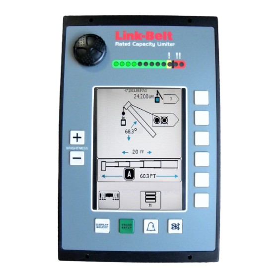
Page 7: The Display
The Operator Alarm key is used to configure operator settable alarms. The Alarm Cancel key is used to mute the Alarm Speaker. Press and hold for seven to ten seconds to cancel the function kick-out in the event of a two-block or overload condition. Link-Belt MG-534 Calibration W450160 10/07... -
Page 8: Calibration Mode
Use of the functions described in this manual requires that the system be in the calibration mode of operation. From the normal working screen, press the “Display/Select” key. BRIGHTNESS DISPLAY CRANE SELECT SETUP Press the key adjacent to “Enter Calibration”. BRIGHTNESS DISPLAY CRANE SELECT SETUP Link-Belt MG-534 Calibration W450160 10/07... - Page 9 5 seconds, calibration will be aborted and the normal working screen will appear. BRIGHTNESS DISPLAY CRANE SELECT SETUP mWARNINg WhEN IN ThE CALIBRATION MODE, ThE TWO-BLOCk ALARM AND fuNCTION kICkOuT ARE DISABLED. Link-Belt MG-534 Calibration W450160 10/07...
-
Page 10: Menu 00 - Error Codes
ANGLE 41.8 information will be displayed. RADIUS 76.2 FT MG534 Main Prog. Press the key adjacent to Exit to return to the main menu. G450052G LENGTH Cal. Serial No. 106.0 0008504G D534147e Exit Link-Belt MG-534 Calibration W450160 10/07... -
Page 11: Group "A" Fault Codes
(W450161). Replace computer. Refer to “Checking the Extension Sensor Drive Voltage” on page 30, “Checking the Boom Extension Sensor Voltage” on page 30, and “Swing Sen- sor” on page 45 of the Troubleshooting manual (W450161). Link-Belt MG-534 Calibration W450160 10/07... - Page 12 Angle Sensor Drive Voltage” on page 33, “Checking the Angle Sensor Volt- age” on page 33, and “Swing Sensor” on page 45 of the Troubleshooting manual (W450161). Internal Temperature Sensor Fault. or higher Replace Computer. Link-Belt MG-534 Calibration W450160 10/07...
-
Page 13: Group "B" Fault Codes
“Function Kickout Fuse (FS2) on page 19 of the Troubleshooting manual (W450161). Replace computer. Check crane circuit breakers. Then, re- fer to “Function Kickout Fuse (FS2) on page 19 of the Troubleshooting manual (W450161). Link-Belt MG-534 Calibration W450160 10/07... -
Page 14: Group "C" Fault Codes
Replace system chip. Refer to “System Chip (IC16)” on page 20 of the Trouble- shooting manual (W450161). Replace computer. Replace system chip. Refer to “System Chip (IC16)” on page 20 of the Trouble- shooting manual (W450161). Link-Belt MG-534 Calibration W450160 10/07... -
Page 15: Group "D" Fault Codes
Swing to correct working area to select chart. Check swing sen- sor zero position, refer to “Swing Sensor Setup and Checks” on page 46 of the Troubleshooting manual (W450161). Check other sensor faults. Reselect crane setup. Check other sensor faults. Reselect crane setup. Link-Belt MG-534 Calibration W450160 10/07... -
Page 16: Menu 01 - Crane Data
“Personality good”, the crane data is working properly. ANGLE 41.8 If the display shows “Personality bad”, the crane data must be RADIUS Personality good 76.2 FT reset. LENGTH 106.0 Press the key adjacent to Reset Crane Personality Data. Exit Link-Belt MG-534 Calibration W450160 10/07... - Page 17 41.8 calibration sequence. If the display continues to show RADIUS Personality good “Personality bad”, contact your service representative. 76.2 FT LENGTH Press the key adjacent to Exit to return to the main menu. 106.0 Exit Link-Belt MG-534 Calibration W450160 10/07...
-
Page 18: Menu 02 - Zero Sensor
106.0 Menu Down Exit Zero Sensor LOAD Press the key adjacent to Zero No. 2 X (where X = actual Zero No.2 input). ANGLE 41.8 RADIUS Menu Up 76.2 FT LENGTH 106.0 Menu Down Exit Link-Belt MG-534 Calibration W450160 10/07... -
Page 19: Boom Angle Sensor Zero
Using a digital level or inclinometer, set the boom to zero Zero No.3 degrees (0°). ANGLE 41.8 Press the key adjacent to Zero No. 3 X (where X = actual RADIUS Menu Up 76.2 FT input). LENGTH 106.0 Menu Down Exit Link-Belt MG-534 Calibration W450160 10/07... - Page 20 When it has finished, the display should show “Zero No. 3 0” Zero No.3 ANGLE Press the key adjacent to Exit to return to the main menu. 41.8 RADIUS Menu Up 76.2 FT LENGTH 106.0 Menu Down Exit Link-Belt MG-534 Calibration W450160 10/07...
-
Page 21: Menu 03 - Span
Enter the measured angle from the inclinometer (use the 41.8 <0> 1 2 3 4 5 6 RADIUS number entry procedure on page 2). 76.2 FT LENGTH 106.0 7 8 9 < . - C Exit Link-Belt MG-534 Calibration W450160 10/07... -
Page 22: Boom Extension Sensor
76.2 FT LENGTH 106.0 Menu Down Exit An optional method for calculating the span is to refer to the crane load chart which will show the fully retracted boom length and the full extended boom length. Link-Belt MG-534 Calibration W450160 10/07... - Page 23 Press the key adjacent to Exit to return to the menu. RADIUS Menu Up 76.2 FT LENGTH 106.0 Menu Down Exit At this stage of the procedure, the boom length display will indicate the fully extended boom length. Retract the boom and continue the procedure. Link-Belt MG-534 Calibration W450160 10/07...
-
Page 24: Menu 04 - Swing Pot Zero
From the previous menu, press the key adjacent to Menu Up 04 Swing Pot to go to “04 Swing Pot”. ANGLE 41.8 Press the key adjacent to 04 Swing Pot. RADIUS Menu Up 76.2 FT LENGTH 106.0 Menu Down Exit Link-Belt MG-534 Calibration W450160 10/07... -
Page 25: Swing Pot Direction
If the numbers decrease (from 359 to 340), press the key LENGTH 106.0 adjacent to Direction = to reverse the direction shown on the Exit display. Press the key adjacent to Exit to return to the menu. Link-Belt MG-534 Calibration W450160 10/07... -
Page 26: Menu 05 - Main Boom Radius/Moment
Press the key adjacent to either Menu Up or Menu Down to 05 Radius/Mom go to “05 Radius/Mom”. ANGLE 41.8 Press the key adjacent to 05 Radius/Mom. RADIUS Menu Up 76.2 FT LENGTH 106.0 Menu Down Exit Link-Belt MG-534 Calibration W450160 10/07... -
Page 27: First Length
Enter Low Radius Enter the radius (use the number entry procedure on page 2). 31.5] ANGLE 0 1 2 3 4 <5>6 RADIUS 31.8 FT LENGTH 38.0 7 8 9 < . - C Exit Link-Belt MG-534 Calibration W450160 10/07... - Page 28 Exit Radius/Mom LOAD The display will show “Bas. 0 (DU)”. Bas.0 (DU) 21.1 ANGLE Press the key adjacent to Bas. 0 (DU). 67.4 Redo Last RADIUS Length 10.7 FT LENGTH 38.0 Redo This Length Exit Link-Belt MG-534 Calibration W450160 10/07...
-
Page 29: Second Length
ANGLE 67.3 0 1 2 3< 4>5 6 RADIUS Measure the radius. 22.6 FT LENGTH Enter the radius (use the number entry procedure on page 2). 75.0 7 8 9 < . - C Exit Link-Belt MG-534 Calibration W450160 10/07... - Page 30 7 8 9 < . - C Exit Radius/Mom LOAD The display will show “Bas. 1 (DU)”. Bas.1 (DU) ANGLE Press the key adjacent to Bas. 1 (DU). 10.0 Redo Last RADIUS Length 67.5 FT LENGTH 75.0 Redo This Length Exit Link-Belt MG-534 Calibration W450160 10/07...
-
Page 31: Third Length
ANGLE Measure the radius. 10.0 0 1 2 3 4 5 6 RADIUS Enter the radius (use the number entry procedure on page 2). 106.9 FT LENGTH 115.0 7 8 <9>< . - C Exit Link-Belt MG-534 Calibration W450160 10/07... - Page 32 7 8 9 < . - C Exit Radius/Mom LOAD The display will show “Bas. 2 (DU)”. Bas.2 (DU) ANGLE Press the key adjacent to Bas. 2 (DU). 64.1 Redo Last RADIUS Length 43.9 FT LENGTH 115.0 Redo This Length Exit Link-Belt MG-534 Calibration W450160 10/07...
- Page 33 Radius/Mom LOAD Press the key adjacent to Yes! Calibrate! to store the data. Yes! Calibrate! ANGLE 64.1 RADIUS 43.9 FT LENGTH 115.0 NO, Exit / Abort Link-Belt MG-534 Calibration W450160 10/07...
-
Page 34: Menu 06 - Boom Deflection Correction
Press the key adjacent to Yes! Calibrate! to start the YES! Calibrate! calibration, otherwise press the key adjacent to No, Exit/ ANGLE 41.8 Abort to cancel. RADIUS 76.2 FT LENGTH 106.0 NO, Exit / Abort Link-Belt MG-534 Calibration W450160 10/07... - Page 35 When entering data below 60°, the warning message, “poor angle” will appear. Use the “high angle” or ‘”low angle” arrow key to identify the angle related to the entry. When this message occurs as the result of an error, correct the error and continue. Link-Belt MG-534 Calibration W450160 10/07...
-
Page 36: Menu 07 - Head Angle
Hang= 0.0 ANGLE 41.8 RADIUS Next Length 76.2 FT LENGTH 106.0 Last L Exit LOAD Press the key adjacent to New Extension. New Extension ANGLE 41.8 RADIUS 0.000 76.2 FT LENGTH 106.0 Exit Link-Belt MG-534 Calibration W450160 10/07... - Page 37 <0> 1 2 3 4 5 6 RADIUS 76.2 FT LENGTH 106.0 7 8 9 < . - C Exit LOAD Press the key adjacent to New Head Angle. New Head Angle ANGLE 41.8 RADIUS 0.000 76.2 FT LENGTH 106.0 Exit Link-Belt MG-534 Calibration W450160 10/07...
- Page 38 Extend the boom to the next length and continue entering data 41.8 RADIUS for up to seven lengths. Next Length 76.2 FT LENGTH Press the key adjacent to Exit to return to the main menu. 106.0 Last L Exit Link-Belt MG-534 Calibration W450160 10/07...
-
Page 39: Menu 08 - Attachments
Press the key adjacent to Yes! Calibrate! to start the YES! Calibrate! calibration, otherwise press the key adjacent to No, Exit/ ANGLE 41.8 Abort to cancel. RADIUS 76.2 FT LENGTH 106.0 NO, Exit / Abort Link-Belt MG-534 Calibration W450160 10/07... - Page 40 41.8 Next Attachment UP RADIUS or Next Attachment Down to select the next desired 76.2 FT attachment. LENGTH 106.0 Next Attachment DN Press the key adjacent to Exit to return to the main menu. Exit Link-Belt MG-534 Calibration W450160 10/07...
-
Page 41: Menu 09 - Winches
Press the key adjacent to Yes! Calibrate! to start the YES! Calibrate! calibration, otherwise press the key adjacent to No, Exit/ ANGLE 41.8 Abort to cancel. RADIUS 76.2 FT LENGTH 106.0 NO, Exit / Abort Link-Belt MG-534 Calibration W450160 10/07... - Page 42 Press the key adjacent to the desired winch or, press the key 41.8 Change Winch RADIUS adjacent to Change Winch to go to change the desired winch 76.2 FT or, press the key adjacent to Exit to return to the main menu. LENGTH 106.0 Exit Link-Belt MG-534 Calibration W450160 10/07...
-
Page 43: Menu 10 - Rope Limits
Press the key adjacent to Yes! Calibrate! to start the YES! Calibrate! calibration, otherwise press the key adjacent to No, Exit/ ANGLE 41.8 Abort to cancel. RADIUS 76.2 FT LENGTH 106.0 NO, Exit / Abort Link-Belt MG-534 Calibration W450160 10/07... - Page 44 Press the key adjacent to Enter RopeLim1 (rear winch) to Enter Rope Lim1 enter the next rope limit or, press the key adjacent to Exit to ANGLE 41.8 return to the main menu. RADIUS 16.800 76.2 FT LENGTH 106.0 Exit Link-Belt MG-534 Calibration W450160 10/07...
-
Page 45: Menu 11 - Alarms
“Yes” and “No”.. RADIUS 76.2 FT Press the key adjacent to Exit to go to the next alarm. LENGTH 106.0 The display will show the next alarm, enable or disable the alarm as desired. Exit Link-Belt MG-534 Calibration W450160 10/07... - Page 46 “Alt Chart” is shown. ANGLE 41.8 RADIUS 76.2 FT LENGTH 106.0 Exit LOAD Press the key adjacent to Exit to return to the main menu. Load Scale ANGLE 41.8 RADIUS 1.000 76.2 FT LENGTH 106.0 Exit Link-Belt MG-534 Calibration W450160 10/07...
-
Page 47: Menu 12 - Digital Inputs
Swing Switch Inputs Interlock/Alt Chart Inputs Interlock/Alt Chart Inputs Not Used Not Used Not Used Not Used Not Used Not Used Not Used Press the key adjacent to Exit to return to the main menu. Link-Belt MG-534 Calibration W450160 10/07... -
Page 48: Menu 13 - Monitor
Len_s(1) = 2.4 WG(1) =460.2 Press the key adjacent to Exit to return to the main menu. RADIUS WT(1) = 21.1 76.2 FT Extn(0) = Head Ang(0) = 0.0 LENGTH 106.0 BDC_fly = -1.59 Exit Link-Belt MG-534 Calibration W450160 10/07... -
Page 49: Menu 15 - Pressure
Rod Side Hydraulic Pressure (actual PSI reading) • Nett Pressure (the difference between piston and rod side pressures scaled by the cylinder geometry). Press the key adjacent to Exit to return to the main menu. Link-Belt MG-534 Calibration W450160 10/07... -
Page 50: Glossary Of Terms
Energy exerted, in this case to support the weight of an object. Geometry A branch of mathematics addressed to the measurement and relationships of points, lines, angles, surfaces, and solids. Graduated Marked with degrees of measurement. Link-Belt MG-534 Calibration W450160 10/07... - Page 51 Stowed attachment An attachment usually stored in an inactive position on the main boom. Superstructure The structural part of a crane above the carrier, usually rotating. Swing The rotation of a crane upper around its centerline. Link-Belt MG-534 Calibration W450160 10/07...
- Page 52 The amount that a body weighs. Write protected An area of memory in a computer that cannot be accessed by a microprocessor for data entry or change. Zero The zero point on a graduated scale. Link-Belt MG-534 Calibration W450160 10/07...
- Page 53 Link-Belt MG-534 Calibration W450160 10/07...
- Page 56 Greer Company is a part of Tulsa Winch Group. www.team-twg.com As a leader in product innovation, Greer Company is committed to the ongoing improvement of its equipment. We reserve the right to make changes to our products without notice. W450160 10/07...
Need help?
Do you have a question about the MG-534 and is the answer not in the manual?
Questions and answers