
Subscribe to Our Youtube Channel
Related Manuals for Q-Pumps QIS Series


Summary of Contents for Q-Pumps QIS Series
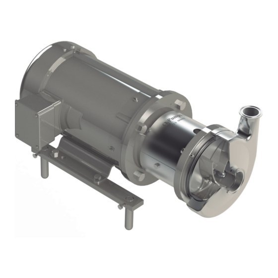
- Page 1 OPERATION AND MAINTENANCE MANUAL Q i s S E R I E S INTERNAL BALANCED MECHANICAL SEAL, CENTRIFUGAL PUMP e n .q -pu mp s. com su p p o r t@ q p u m ps .co m 02-11...
-
Page 2: Table Of Contents
OPERATION AND MAINTENANCE MANUAL QIS SERIES Centrifugal Pump Thank you for purchasing a Q-Pumps product This manual contains installation, operation, cleaning and maintenance instructions for the QIS Series. It also includes a part list as well as a troubleshooting chart to assist in determining pump malfunction and practical advices for the maintenance and operation of the equipment. - Page 3 Q-Pumps S.A. de C.V. Warranty Q-Pumps guarantees that all manufactured and sold products are free from defects in materials and manufacture for a period of one (1) year from the date of shipment. The warranty does not apply to products which require repair or replacement due to what is considered normal wear.
-
Page 4: Safety
Indicates a potentially hazardous situation WITHOUT GUARD IN PLACE which, if not avoided, could result in death or serious injury. Safety labels are placed on every pump. DO NOT remove any labeling on any Q-Pumps product. Replace any label that is missing. QIS SERIES-M02... -
Page 5: Instalation
Before servicing pump, disconnect electrical power source. The QIS series closed-coupled pumps are made up of two sections, power or drive section and the liquid end or pump section. The pump is mounted to the frame of the drive motor by means of an adapter, and is coupled to the motor shaft. -
Page 6: Assembly Preliminaries
OPERATION AND MAINTENANCE MANUAL QIS SERIES Centrifugal Pump ASSEMBLY PRELIMINARIES WARNING Before servicing pump, disconnect electrical power source, carefully relieve all pressure and drain all fluids from pump and connected piping. Before beginning the assembly procedure identify every element that is going to be installed, you can use the exploded view and part list shown in pages 7 and 8. -
Page 7: Qis General Diagram
OPERATION AND MAINTENANCE MANUAL QIS SERIES Centrifugal Pump Q I S G E NE R AL D IAG R AM QIS SERIES-M02... -
Page 8: Qis Part List
OPERATION AND MAINTENANCE MANUAL QIS SERIES Centrifugal Pump Q I S PART LI ST ITEM PART DESCRIPTION CASING CASING O-RING IMPELLER NUT PLUS IMPELLER NUT GASKET IMPELLER QIS MECHANICAL SEAL ROTARY HOLDER INTERNAL ROTARY FACE STATIC FACE EXTERNAL ROTARY FACE (DOUBLE MECHANICAL SEAL) -
Page 9: Start The Assambly
OPERATION AND MAINTENANCE MANUAL QIS SERIES Centrifugal Pump START THE A SS E MB LY It is highly recommended that you use the general diagram to identify the components and thus be able to carry out the assemblies and sub-assemblies that will be explained below. -
Page 10: Assembly The Adapter To The Motor
OPERATION AND MAINTENANCE MANUAL QIS SERIES Centrifugal Pump 2 . A SS E M B LY O F TH E ADAP TE R TO TH E M OTO R Place the stainless adapter (15) on the motor flange and fix it with hexagonal screws and tighten to the torque values recommended in chart 1. -
Page 11: Spacing Of The Impeller And Stub Shaft
OPERATION AND MAINTENANCE MANUAL QIS SERIES Centrifugal Pump 3 . S PACI N G O F TH E I M PE LLE R AN D STU B S HAF T The correct operation of the pump depends on the separation of the impeller (5) from the backplate (7) and the fixation of the stub shaft (10) on the motor shaft. - Page 12 OPERATION AND MAINTENANCE MANUAL QIS SERIES Centrifugal Pump 3 c . Place only the rotary holder of the mechanical seal (6A) together with its respective O-ring (6H) until it seats on the shoulder of the stub shaft. Put the impeller key (12) on the keyway of the stub shaft.
- Page 13 OPERATION AND MAINTENANCE MANUAL QIS SERIES Centrifugal Pump 3 d . Once the assembly is tightened, place a spacer between the back of the impeller and the front of the backplate. Use a spacer of 0.025” (0.63 mm) thru 0.030” (0.76 mm) for models 114, 214, 216 &...
-
Page 14: Assembling The Single Mechanical Seal
OPERATION AND MAINTENANCE MANUAL QIS SERIES Centrifugal Pump 3 e. Use the 3/8” rod, the hexagonal socket and wrench to untighten the impeller nut in order to remove the elements previously assembled. Take the impeller nut, impeller gasket, impeller and impeller key off. Do not forget to remove also the spacer used to determinate the stub shaft position. - Page 15 OPERATION AND MAINTENANCE MANUAL QIS SERIES Centrifugal Pump Internal Rotary Seal Sub-Assembly First place the spring (6E) into the rotary holder (6A), the cut side has to be centered with the pin inside the rotary holder; it is recommended to place the tips of the spring touching the rotary holder inside surface.
- Page 16 OPERATION AND MAINTENANCE MANUAL QIS SERIES Centrifugal Pump Tight the assembly as it is indicated in step 3c. For models 114 and 214 use a torque of 4d . 25 ft.lb and a torque of 40 ft.lb for the rest of the models when tightening the impeller nut.
- Page 17 OPERATION AND MAINTENANCE MANUAL QIS SERIES Centrifugal Pump 5 b. Place into the backplate seal housing the stationary face of the mechanical seal (6C) with its O-rings (6J & 6K). First place the O-ring (6J) on the stationary face groove, then the O-ring (6K) on the back.
- Page 18 OPERATION AND MAINTENANCE MANUAL QIS SERIES Centrifugal Pump 5d . Now insert the whole rotary seal sub-assembly into the stub shaft, this will contact the stationary seal face placed previously in the backplate. Push to compress the assembly and then insert the impeller key into the stubshaft. Place the O-ring (6G) onto the stubshaft end;...
- Page 19 OPERATION AND MAINTENANCE MANUAL QIS SERIES Centrifugal Pump Finally place the racor flushes (9) on to the backplate, one on top and one at the bottom. It is recommended to feed from an external line clean water to the double mechanical seal with a pressure of 10 to 15 psi maximum.
-
Page 20: Assembling The Casing
OPERATION AND MAINTENANCE MANUAL QIS SERIES Centrifugal Pump 5 . A SS E M B LI N G TH E CA SS I N G 6a . Once the mechanical seal has been installed and the impeller and impeller nut assembly has been tightened, place the casing O-ring (2) onto the groove on the front of the backplate. - Page 21 OPERATION AND MAINTENANCE MANUAL QIS SERIES Centrifugal Pump Turning by hand the impeller, check that it does not rubs against the casing. The assembly may turn easily without restriction. If there is any sound or sensation of rubbing, you need to check the whole assembly, disassemble and start again.
-
Page 22: Common Problems
Centrifugal Pump QUICK GUIDE FOR SOLVING COMMON PROBLEMS Q-Pumps products are relatively easy to maintain with the exception of the sanitary process. Just as with any other element of machining, problems may arise. This section offers a guide for identifying and correcting the majority of the pumping problems. For problems with you motor, contact the manufacturer directly for best assistance. - Page 23 OPERATION AND MAINTENANCE MANUAL QIS SERIES Internal Balanced Mechanical Seal, Centrifugal Pump cceso A # 103 Fracc. Industrial Jurica Querétaro, Qro. Mexico. 76130 Call: +52 (442) 103 31 00 For Technical support contact: support@qpumps.com For Sales support contact: sales@qpumps.com en.q-pumps.com...
Need help?
Do you have a question about the QIS Series and is the answer not in the manual?
Questions and answers