SystemAir Topvex FR03 Installation Instructions Manual
Compact air handling unit
Hide thumbs
Also See for Topvex FR03:
- Operation and maintenance instructions (34 pages) ,
- Operation and maintenance instruction (26 pages) ,
- Installation instructions manual (24 pages)

Related Manuals for SystemAir Topvex FR03


Summary of Contents for SystemAir Topvex FR03
- Page 1 Topvex FR03, FR06, FR08, and FR11 Compact Air Handling Unit Installation instructions 206638-EN_GB 100113 V.10-01 (C. 1.2-1-00)
-
Page 2: Table Of Contents
Contents 1 Warnings........................... 1 2 Declaration of Conformity ......................2 3 Product Introduction ........................3 3.1 General ........................... 3 3.2 Technical Data ......................... 4 3.3 Transport and Storage ...................... 6 4 Installation..........................7 4.1 Where to Install the Unit....................7 4.2 Unpacking........................ -
Page 3: Warnings
• Do not connect tumble dryers to the ventilation system • Take care not to damage the water battery when connecting water pipes to connectors. Use a spanner to tighten the connection. Topvex FR03, FR06, FR08, and FR11 Installation instructions Systemair AB... -
Page 4: Declaration Of Conformity
SS-EN ISO 1 Safety of machinery; basic 2100–1:2003 concepts, general principles for design; Part 1: Basic terminology, methodology Topvex FR03, FR06, FR08, and FR11 Installation instructions Systemair AB 206638... -
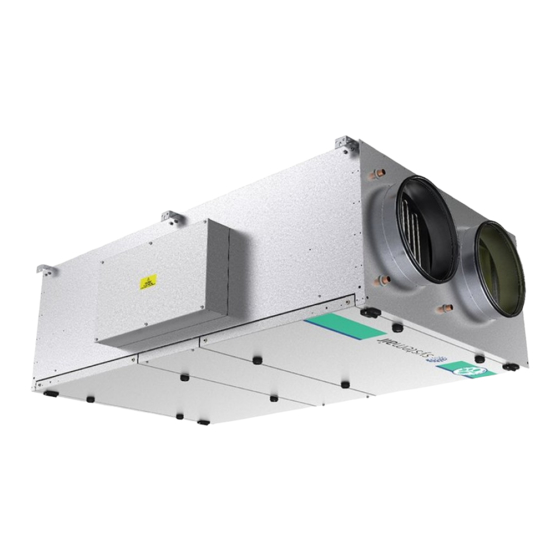
Page 5: Product Introduction
This installation manual concerns air handling unit type TopvexFR03, FR06, FR08, and FR11 manufactured by Systemair AB. It consists of basic information and recommendations concerning the design, installation, start-up and operation, to ensure a proper fail-free operation of the unit. -
Page 6: Technical Data
1902 1250 FR08 2230 1520 ⌀500 2002 1450 FR11 2440 1720 ⌀630 2202 1650 Model Weight (kg) FR03 FR06 1000 FR08 1050 FR11 1150 Y: 15R 1/2″ Inner thread Topvex FR03, FR06, FR08, and FR11 Installation instructions Systemair AB 206638... - Page 7 400 V 3N~ 230V 3~ FR03 EL — FR03 HW FR06 EL 1837 — FR06 HW 1837 FR08 EL 1944 — FR08 HW 1944 FR11 EL 5666 — FR11 HW 5666 Topvex FR03, FR06, FR08, and FR11 Installation instructions Systemair AB 206638...
-
Page 8: Transport And Storage
3.3 Transport and Storage The Topvex FR03, FR06, FR08, and FR11 should be stored and transported in such a way that it is protected against physical damage that can harm panels, handles, display etc. It should be covered so that dust, rain and snow cannot enter and damage the unit and its components. The appliance is delivered in one piece containing all necessary components, wrapped in plastic on a pallet for easy transportation figure 3. -
Page 9: Installation
4.2 Unpacking Verify that all ordered equipment are delivered before starting the installation. Any discrepancies from the ordered equipment must be reported to the supplier of Systemair products. Topvex FR03, FR06, FR08, and FR11 Installation instructions... -
Page 10: Installing The Unit
Installation flat on the ground. Left and right connections are possible Ceiling installation. Left and right connections are possible Horizontal wall installation, not allowed Vertical wall installation, not allowed Topvex FR03, FR06, FR08, and FR11 Installation instructions Systemair AB 206638... - Page 11 Make sure to use proper fastening device (screw/bolts) considering the weight of the unit and the type of surface it is fitted to. The installation can only be performed by an authorized installer. Topvex FR03, FR06, FR08, and FR11 Installation instructions Systemair AB 206638...
-
Page 12: Supply Air Sensor
Other temperature sensors are built in to the unit from factory. The supply air sensor is enclosed in the unit package on delivery Fig. 7 Installed supply air sensor Topvex FR03, FR06, FR08, and FR11 Installation instructions Systemair AB 206638... -
Page 13: Installing The Control Panel
Maximum length between control panel and unit is 10 m as standard. If needed, drill two holes in the wall to hang the control panel (center to center: 60 mm) (pos.1 figure 9). Topvex FR03, FR06, FR08, and FR11 Installation instructions Systemair AB 206638... - Page 14 Fig. 9 Control panel wire connections Position Description Mounting holes Connection block Connection to yellow cable Connection to orange cable Connection to red cable Connection to brown cable Connection to black cable Topvex FR03, FR06, FR08, and FR11 Installation instructions Systemair AB 206638...
-
Page 15: Connections
All ducts installed in cold rooms/areas must be well insulated. Use insulating covering (minimum 100 mm mineral wool) with plastic Topvex FR03, FR06, FR08, and FR11 Installation instructions Systemair AB... -
Page 16: Water Connections
Cover plates around the pipes are fixed to the unit (reinforcement). Caution Take care not to damage the water battery when connecting water pipes to connectors. Use a spanner to tighten the connection. Topvex FR03, FR06, FR08, and FR11 Installation instructions Systemair AB 206638... -
Page 17: Electric Connections
24V AC Max. 2,0 A continuous load AI Ref Sensor supply air reference AI 1 Sensor supply air 1. These inputs may only be wired to voltage free contacts Topvex FR03, FR06, FR08, and FR11 Installation instructions Systemair AB 206638... - Page 18 24V AC Max. 2,0 A continuous load AI Ref Sensor supply air reference AI 1 Sensor supply air 1. These inputs may only be wired to voltage free contacts Topvex FR03, FR06, FR08, and FR11 Installation instructions Systemair AB 206638...
- Page 19 Exoline and Modbus connections are to be connected directly to the Corrigo controller situated in the electrical connection box on terminal 50-53 (B, A, N, E) see figure 12. Fig. 12 BMS connection on Corrigo Topvex FR03, FR06, FR08, and FR11 Installation instructions Systemair AB...
-
Page 20: Additional Equipment
For information concerning additional external equipment such as valve actuators, motorized dampers, E-tool, roof units, wall grilles etc. see technical catalogue and their enclosed instructions. For electrical connections of external components see enclosed wiring chart. Topvex FR03, FR06, FR08, and FR11 Installation instructions Systemair AB... - Page 21 Topvex FR03, FR06, FR08, and FR11 Installation instructions Systemair AB 206638...
- Page 22 Systemair AB reserves the right to make changes and improvements to the contents of this manual without prior notice. Systemair AB Industrivägen 3 739 30 Skinnskatteberg, Sweden Phone +46 222 440 00 Fax +46 222 440 99 www.systemair.com 206638...
Need help?
Do you have a question about the Topvex FR03 and is the answer not in the manual?
Questions and answers