Unipower UP-2210 Installation And Configuration Manual
Hide thumbs
Also See for UP-2210:
- Hardware installation and configuration manual (90 pages) ,
- Hardware installation and configuration manual (119 pages)

Related Manuals for Unipower UP-2210


Summary of Contents for Unipower UP-2210
- Page 1 UNIPOWER UP-2210R/P UP-2210R/P Hardware installation and configuration manual English version 20.0...
-
Page 2: Introduction
PQ Secure is the result of targeted efforts by Unipower and our customers to create an advanced, user-friendly and reliable power quality monitoring system. -
Page 3: Table Of Contents
UNIPOWER UP-2210R/P Hardware installation and configuration manual INTRODUCTION ................................2 SAFETY INFORMATION ............................5 ..........................5 NSTALLATION CONDITIONS ........................... 5 NSTALLING THE INSTRUMENT ..............................6 OWER SUPPLY ..............................6 SED PRODUCTS UNDERTAKING AND WARRANTY ........................6 ................................6 IABILITY ..............................6 ARRANTIES ................................ - Page 4 UNIPOWER UP-2210R/P Hardware installation and configuration manual RS-485................................45 GDW-11 GSM/GPRS- RS-485 ......46 SING MULTIPLE METERS WITH ESTERMO MODEM AND GPS CLOCK SYNCHRONISATION MODULE ....................49 INSTALLATION ............................50 8.1.1 GPS communication configuration ......................50 IRIG-B................................50 GPS......................50...
-
Page 5: Safety Information
Only authorized and well-informed personnel must use the instrument, because normal use of the instrument involves dangerous high voltages, which can cause death or serious injury. Only trained Unipower personnel may carry out any intervention in the instrument. Installation conditions Make sure the area in which you plan to install the meter is clean, dry and dust-free. -
Page 6: Power Supply
In the event of a claim for repair under the warranty, Unipower AB is entitled to choose whether to repair or to replace the product. The purchaser's claim under the warranty must be made in writing to Unipower AB before the warranty expires. -
Page 7: Patent
UNIPOWER UP-2210R/P Hardware installation and configuration manual obligations above, Unipower AB is not bound by other warranties or obligations unless these have been agreed between the parties or are imposed by law. Patent Unipower AB´s products are covered by one or more of the following patents/patent applications: Swedish Pat. -
Page 8: Components Of The Pq Secure System
UNIPOWER UP-2210R/P Hardware installation and configuration manual COMPONENTS OF THE PQ SECURE SYSTEM PQ Secure system is a collective name for a permanently installed measuring system for the continuous monitoring of power quality in the electricity network. It consists of three parts - the measuring device, communication equipment and a computer for storing the measured data. -
Page 9: Measuring Device
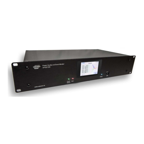
UNIPOWER UP-2210R/P Hardware installation and configuration manual Measuring device The measuring device UP-2210 is an advanced, 3-phase power quality and disturbance analyser designed for permanent installation. There are different models, UP-2210 wall mount and UP- 2210R/P rack/panel mount. UP-2210 Rack and panel mount... -
Page 10: Portable Meter Unilyzer 900 / Unilyzer 900C
UNIPOWER UP-2210R/P Hardware installation and configuration manual Portable meter Unilyzer 900 / Unilyzer 900c The meters Unilyzer 9900/900c are portable power quality and disturbance analysers. They can also be integrated in a PQ Secure system together with permanently installed meters. -
Page 11: Server Performance
Server performance 3.4.1 The required server performance depends on which PQ Secure application is being used. Unipower or our representatives can help you with choosing the right computer/server solution. Data growth in the database is approximate 29 MB to 75 MB per Meter per Month (MM) depending on configuration. -
Page 12: Installing Permanent Meter Up-2210R/P
UNIPOWER UP-2210R/P Hardware installation and configuration manual INSTALLING PERMANENT METER UP-2210R/P The installation process involves fitting the measuring device in an existing equipment cabinet or similar meter at the selected installation site. This includes the connection to existing instrument transformers and the chosen communication equipment. The connection to the instrument transformers must only be made by qualified electrical installers or equivalent personnel to prevent injury during installation. - Page 13 Note: If the meters are used with external/internal modem, keep in mind that phone lines are easily affected by lightning. Modems usually don’t have lightning protection. Unipower recommends that external lightning protection is installed between the phone line and modem in exposed locations, in order to protect the meter from damages caused by lightning.
-
Page 14: Installation Diagram
UNIPOWER UP-2210R/P Hardware installation and configuration manual Installation diagram The UP-2210R meter can be mounted on a rack/panel. For mounting dimensions, refer to the drawing below. It is important to install the meter as close as possible to the measured object. When installing the unit, also bear in mind the type of communication facility you will be using, for example close to the window for a GSM modem, near a telephone outlet for an external modem, etc. - Page 15 16 inputs. The digital inputs are used for a range of applications, providing completely new monitoring opportunities. The UP-2210 can for example be used as a fault meter. You have the option of capturing various types of power quality events, for example...
- Page 16 If an AC supply is used, the phase is connected to L input and the neutral conductor is connected to the negative input, N on the UP-2210 meter. Always ensure that the UP-2210 unit is grounded (earthed), using the input marked with the ground symbol.
-
Page 17: Connection Alternatives
In the electric grid there are multiple configurations of instrument transformers (PT= Potential Transformer, CT= Current Transformer). The UP-2210 meters support all standard 1-phase and 3- phase connections. The meter is configured using PQ Online, where all the common connections methods with their respective wiring diagrams available and a graphical explanation. -
Page 18: Phase With 4 Wire Measurement With Direct Voltage And 3 Ct's
UNIPOWER UP-2210R/P Hardware installation and configuration manual 3 phase with 4 wire measurement with direct voltage and 3 CT’s 4.4.1 Figure 10 The above wiring diagram is used for 3-phase measurement in low voltage networks. The voltage channel of the unit is connected directly to the electricity network for measuring line-to-neutral voltage (230 V) and therefore do not require an instrument transformer (PT). -
Page 19: Phase With 4 Wire Measurement With Direct Voltage And 2 Ct's
UNIPOWER UP-2210R/P Hardware installation and configuration manual 3 phase with 4 wire measurement with direct voltage and 2 CT’s 4.4.2 Figure 11 The above wiring diagram is used for 3-phase measurement in low voltage networks. The voltage channel of the unit is connected directly to the electricity network for measuring line-to-neutral voltage (230 V) and therefore do not require an instrument transformer (PT). -
Page 20: Phase With 4 Wire Measurement With 3 Ct's And 3 Pt's
UNIPOWER UP-2210R/P Hardware installation and configuration manual 3 phase with 4 wire measurement with 3 CT’s and 3 PT’s 4.4.3 Figure 12 The above wiring diagram is used for three-phase measurement in public distribution networks with 3 CT´s and 3 PT’s. The voltage channels of the unit are connected to PT’s (normally 63 V AC secondary), for supplying line-to-earth voltages, and current channels are connected to CT´s... -
Page 21: Phase With 4 Wire Measurement With 2 Ct's And 3 Pt's
UNIPOWER UP-2210R/P Hardware installation and configuration manual 3 phase with 4 Wire measurement with 2 CT’s and 3 PT’s 4.4.4 Figure 13 The above wiring diagram is used for three-phase measurement in in public distribution networks with 2 CT´s and 3 PT’s. The voltage channels of the unit are connected to PT’s (normally 63 V AC secondary to earth), for supplying line-to-line voltages, and current channels are connected to CT´s... -
Page 22: Phase With 4 Wire Measurement With 3 Ct's And 2 Pt's
UNIPOWER UP-2210R/P Hardware installation and configuration manual 3 phase with 4 wire measurement with 3 CT’s and 2 PT’s 4.4.5 Figure 14 The above wiring diagram is used for three-phase measurement in in public distribution networks with 3 CT´s and 2 PT’s. The voltage channels of the unit are connected to PT’s (normally 63 V AC secondary to earth), for supplying line-to-line voltages, and current channels are connected to CT´s... -
Page 23: 3-Phase 4 Wire Measurement With 2 Ct's And 2 Pt's
UNIPOWER UP-2210R/P Hardware installation and configuration manual 3-phase 4 wire measurement with 2 CT’s and 2 PT’s 4.4.6 Figure 15 The above wiring diagram is used for three-phase measurement in public distribution networks with 2 CT´s and 2 PT’s. The voltage channels of the unit are connected to PT’s (normally 63 V AC secondary to earth), for supplying line-to-line voltages, and current channels are connected to CT´s... -
Page 24: 1-Phase Measurement With Direct Voltage And One Ct (Line-To-Neutral Voltage)
UNIPOWER UP-2210R/P Hardware installation and configuration manual 1-phase measurement with direct voltage and one CT (Line-to-neutral voltage) 4.4.7 Figure 16 The above wiring diagram is used for single-phase measurement in low voltage networks. The voltage channel of the unit is connected directly to the public distribution networks for measuring line-to-neutral voltage (230 V) and therefore do not require an instrument transformer (PT). -
Page 25: 1-Phase Measurement With One Pt And One Ct
UNIPOWER UP-2210R/P Hardware installation and configuration manual 1-phase measurement with one PT and one CT 4.4.8 Figure 17 The above wiring diagram is used for single-phase measurement in public distribution networks with one CT and one PT. The voltage channel of the unit is connected to PT for measuring line-to-neutral voltage. -
Page 26: Hv 3-Phase Measurement With 2 Ct's And 2 Pt's (Line-To-Line Voltages)
UNIPOWER UP-2210R/P Hardware installation and configuration manual HV 3-phase measurement with 2 CT’s and 2 PT’s (Line-to-line voltages) 4.4.9 Figure 18 The above wiring diagram is used for three-phase measurement in public distribution networks with 2 CT´s and 2 PT’s. The voltage channels of the unit are connected to PT’s for measuring line-to-line. -
Page 27: Hv 3-Phase Measurement With 3 Ct's And 2 Pt's (Line-To-Line Voltages)
UNIPOWER UP-2210R/P Hardware installation and configuration manual HV 3-phase measurement with 3 CT’s and 2 PT’s (Line-to-line voltages) 4.4.10 Figure 19 The above wiring diagram is used for three-phase measurement in public distribution networks with 3 CT´s and 2 PT’s. The voltage channels of the unit are connected to PT’s (normally 110 V AC secondary), for supplying line-to-line voltages, and current channels are connected to CT’s (normally... -
Page 28: Hv 3-Phase Measurement With 2 Ct's And 3 Pt's (Line-To-Line Voltages)
UNIPOWER UP-2210R/P Hardware installation and configuration manual HV 3-phase measurement with 2 CT’s and 3 PT’s (Line-to-line voltages) 4.4.11 Figure 20 The above wiring diagram is used for three-phase measurement in in public distribution networks with 2 CT’s and 3 PT’s. The voltage channels of the unit are connected to the PT’s (normally 63 V AC secondary to earth), for supplying line-to-line voltages, and current channels are connected to the CT´s (normally 1 - 5 A AC secondary). -
Page 29: Hv 3-Phase Measurement With 3 Ct's And 3 Pt's (Line-To-Line Voltages)
UNIPOWER UP-2210R/P Hardware installation and configuration manual HV 3-phase measurement with 3 CT’s and 3 PT’s (Line-to-line voltages) 4.4.12 Figure 21 The above wiring diagram is used for three-phase measurement in public distribution networks with 3 CT´s and 3 PT’s. The voltage channels of the unit are connected to PT’s (normally 63 V AC secondary to earth), for supplying line-to-line voltages, and current channels are connected to CT´s... -
Page 30: 3-Phase Measurement With Direct Voltage, 2 Ct´s (Line-To-Neutral)
UNIPOWER UP-2210R/P Hardware installation and configuration manual 3-phase measurement with direct voltage, 2 CT´s (Line-to-neutral) 4.4.13 Figure 22 The above wiring diagram is used for 3-phase measurement in low voltage networks. The voltage channel of the unit is connected directly to the electricity network for measuring line-to-neutral voltage (230 V) and therefore do not require an instrument transformer (PT). -
Page 31: 3-Phase Measurement With Direct Voltage, 3 Ct´s And Neutral (Line-To-Neutral Voltages)
UNIPOWER UP-2210R/P Hardware installation and configuration manual 3-phase measurement with direct voltage, 3 CT´s and neutral (Line-to-neutral voltages) 4.4.14 Figure 23 The above wiring diagram is used for 3-phase measurement in low voltage networks. The voltage channel of the unit is connected directly to the electricity network for measuring line-to-neutral voltage (230 V) and therefore do not require an instrument transformer (PT). -
Page 32: Split Phase 2Ct 2Pt
UNIPOWER UP-2210R/P Hardware installation and configuration manual Split Phase 2CT 2PT 4.4.15 Figure 24 The above wiring diagram is used for Channel: Measured object: Channel: Measured object: (Neutral) -
Page 33: Sp 2Ct Dv
UNIPOWER UP-2210R/P Hardware installation and configuration manual SP 2CT DV 4.4.16 Figure 25 The above wiring diagram is used for Channel: Measured object: Channel: Measured object: (Neutral) -
Page 34: Hv/Mv Earth Fault Monitoring Via Channel U4
UNIPOWER UP-2210R/P Hardware installation and configuration manual HV/MV Earth fault monitoring via channel U4 4.4.17 In high impedance grounded MV networks the voltage in the transformer’s ground point is of interest to study. Earth faults and emerging earth faults can be detected by analyzing the ground point voltage. -
Page 35: Vector Graph For Correct Connection
UNIPOWER UP-2210R/P Hardware installation and configuration manual Vector graph for correct connection To check and certify a correct connection of the measuring device you can use the program PQ Online. In PQ Online, under “Real time Analysis” a tab called “Vector”. This tool is a good controller to verify that you have plugged in phases correctly and turned the ammeters in the right direction. -
Page 36: Recommended Practices
HV networks are 3-phase, 3-wire networks without neutral conductor. Direct grounding is common here. Connect your UP-2210 to measure line-line voltages U1-U3 and phase currents I1-I3 according to one of the sections 4.4.9, 4.4.10, 4.4.11 and 4.4.12 depending on how many PT/CT there are. -
Page 37: Isolated (Ungrounded) 3-Wire Systems
In a 3-phase, 3-wire network without neutral conductor it is also common to isolate the network and leave it ungrounded. Connect your UP-2210 to measure line-line voltages U1-U3 and phase currents I1-I3 according to one of the sections 4.4.9, 4.4.10, 4.4.11 and 4.4.12 depending on how many PT/CT there are. -
Page 38: Connection Of Digital Inputs
If you have signals with normally high values, active, you can via the configuration in PQ Online invert the signal to trigger events when the signal drops to zero. Other equipment UP-2210 or system Figure 29 Connection of digital outputs 4.7.2... -
Page 39: Substation Display
UNIPOWER UP-2210R/P Hardware installation and configuration manual Substation display There is an optional substation display unit that can be installed in a panel and serve a number of (up to 20) meters. Figure 31 From the substation display realtime values can be viewed and meter configuraton can be done. -
Page 40: Pq Online Substation Display Configuration
UNIPOWER UP-2210R/P Hardware installation and configuration manual PQ Online substation display configuration 1. Create a connection using either Ethernet or USB. Figure 33 2. Repeat for each meter in the substation. 3. Launch the Panel display setup Figure 34 4. Select the previously saved configuration from the Connection drop down list and select which starting view to show when PQ Online 3 opens. -
Page 41: Display
UNIPOWER UP-2210R/P Hardware installation and configuration manual Display On the front side of the UP-2210R there is a display that can show voltage and current values in real- time. Several parameters can be shown, such as, Voltage values, current values, harmonics, flicker, power frequency etc. -
Page 42: Installing Communication Equipment
(2G/3G) and technology the router uses. Commonly supported protocols are GPRS, EDGE, HSDPA and UTMS. To use a router with a meter (UP-2210 or UP-2210R etc.) the following must be done: The SIM card used must have no PIN-code and it must have a public, static IP-address. - Page 43 UNIPOWER UP-2210R/P Hardware installation and configuration manual Figure 37 Note how UDP 16427 is routed to UDP 16421 IP 192.168.1.7. The meter given the IP 192.168.1.7 will respond to communication on UDP port 16427 to the router’s (actually the SIM card’s) public...
- Page 44 UNIPOWER UP-2210R/P Hardware installation and configuration manual shows UP-2210R connected to a 3G router: Standard switch Figure 38 GPRS or 3G router The standard switch is only needed when there are multiple meters that needs internet access.
- Page 45 1 km. It may also be necessary to terminate (jumper) the contacts (A to B) on the UP-2210 with a 120 Ω resistor to improve the communication conditions. In this case, the resistor is only connected in the last unit.
-
Page 46: Using Multiple Meters With Westermo Gdw-11 Gsm/Gprs-Modem And Rs-485
UNIPOWER UP-2210R/P Hardware installation and configuration manual Using multiple meters with Westermo GDW-11 GSM/GPRS-modem and RS-485 The Westermo GDW-11 is an example of an industry GSM/GPRS modem with both RS-485. The RS-485 is an easy solution if you want to connect one or several meters to one wireless modem/SIM card. - Page 47 UNIPOWER UP-2210R/P Hardware installation and configuration manual...
- Page 48 UNIPOWER UP-2210R/P Hardware installation and configuration manual If you want to use the modem with RS-232 communication, change S1-4 from on to off. Power the modem off-on to make changes active.
-
Page 49: Gps Clock Synchronisation Module
The GPS clock synchronization module can be used with the Unipower UP-2210. In order for the synchronization to work, the units must be equipped with the appropriate software as well as the necessary peripheral hardware. -
Page 50: Installation
UP-2210R/P Hardware installation and configuration manual INSTALLATION The GPS adapter connects to the UP-2210 via the Display Port (RJ45 connector) via a special DIN- mounted GPS adapter, or via the RS232 port. The following sections will describe the different connection methods in detail. -
Page 51: Gps Connection Instruction For Up2210/Up2210R
UP2210 or a UP2210R measurement instruments. To perform this installation, you will need: A Garmin GPS16x-LVS antenna. Unipower article no: 22-4042. A UP2210 or UP2210R with the 22-4052 module installed. 4 wire signal/connection cable (for several UP2210/UP2210R to the same GPS) ... - Page 52 UNIPOWER UP-2210R/P Hardware installation and configuration manual 4Blue 5White 6Grey 7Green 8Purple Figure 45-RJ45 connector...
- Page 53 UNIPOWER UP-2210R/P Hardware installation and configuration manual 2. When you have identified the cables and noted them, cut of the RJ45 connector from the cable. Figure 46-RJ45 connector separated 3. Strip approximately 30mm from your cable. Keep the individual cables identified as number 1,2,3,5 and 6.
- Page 54 UNIPOWER UP-2210R/P Hardware installation and configuration manual 4. Strip each individual cable (it is highly recommended to use cable ferrules) and connect each cable to the pluggable terminal block that was supplied with the instrument. The order of connection is (Seen from the right, please also see Figure 48 for reference) 1.
-
Page 55: Attaching Several Up2210/Up2210R To The Same Gps
UNIPOWER UP-2210R/P Hardware installation and configuration manual Attaching several UP2210/UP2210R to the same GPS It is easy to attach several adjacent instruments to the same GPS. Use suitable installation cable and connect the green, white and black wires in the terminal plug to each terminal in parallel. See figure below. -
Page 56: Installing Software
UNIPOWER UP-2210R/P Hardware installation and configuration manual Installing Software All programs that form part of the PQ Secure system can be found on the supplied installation CD. Installation procedure Depending on the architecture of the PQ Secure the different programs should be installed on different computers. -
Page 57: Installing Pq Online
Browse button to open the file "Setup.exe" in the PQOnline\Disk1 folder, and click on OK. Installing UniLauncher 9.3.1 UniLauncher is a utility application that helps you to connect to your Unipower meters via USB. When you connect the USB cable UniLauncher will automatically connect with the meter and launch PQ Online. - Page 58 UNIPOWER UP-2210R/P Hardware installation and configuration manual Figure 51 We recommend the above default settings. The path to the folder in Figure 51A is the location where data will be automatically downloaded by UniLauncher. To use UniLauncher, first connect the USB cable to the meter. Then connect it to the PC. After a few seconds you should see a message that the meter is being connected and then a menu like in .
-
Page 59: Pq Online
UP-2210R/P Hardware installation and configuration manual PQ ONLINE PQ Online is mainly used for configuring the measuring devices UP-2210R, UP-2210 and Unilyzer 900/900C, but is also used as a communication program between the measure site and the office. In that case, PQ Online is used for the manual polling of measure data or for real-time analysis. - Page 60 UNIPOWER UP-2210R/P Hardware installation and configuration manual SmartCom Server Here you specify the meters Serial number, Password and Host name. Figure 55 Select the appropriate alternative and click the Connect button. The status window enables you to follow the communication process.
-
Page 61: Measurement Settings
UNIPOWER UP-2210R/P Hardware installation and configuration manual Measurement settings 10.2 Figure 56 In measurement setting you can view information about the actual settings, see Figure 56. Wire-connection configuration. Settings wizard, 10.2.1 You can use the settings wizard that guide you through the configuration of your meter. Press Setting... - Page 62 UNIPOWER UP-2210R/P Hardware installation and configuration manual A. New setting When choosing new setting you will get four ways of selecting power transformer configuration as Figure 58 show. Select the actual configuration. Figure 58 Example below shows how to choose a four wire 3 phase configuration with 3 CT’s and 3 PT’s Select four-wire wye as instrument transformer configuration.
- Page 63 UNIPOWER UP-2210R/P Hardware installation and configuration manual Enter measurement transformer nominal level. Additional constants. Can be used for turning current reference by entering -1. Figure 60 In the example above, Figure 60, the primary voltage is 11 kV and the secondary 110 V.
- Page 64 UNIPOWER UP-2210R/P Hardware installation and configuration manual Advanced settings are described in chapter 0 Figure 63 Press Next and enter Measure setting name and signature and press Finish to save the settings to the meter. See Fel! Hittar inte referenskälla. below.
- Page 65 UNIPOWER UP-2210R/P Hardware installation and configuration manual B. Use the active setting. You can use the active settings and modify this and then save as a new configuration. Information about the actual highlighted parameter. Figure 65 In example above, Figure 65, the primary voltage is 11 kV and the secondary 110 V.
- Page 66 UNIPOWER UP-2210R/P Hardware installation and configuration manual Figure 67 Press Next and enter Measure setting name and signature and press Finish to save the settings to the meter, see Fel! Hittar inte referenskälla. below. If you want to save the settings to a file choose Save to file…...
-
Page 67: Advanced Settings
UNIPOWER UP-2210R/P Hardware installation and configuration manual Advanced settings 10.2.2 In advanced settings you have five overall setting icons. A. General settings B. Measure site properties C. Storage intervals D. Disturbance E. Slowscan settings These are described below. A. General settings... - Page 68 UNIPOWER UP-2210R/P Hardware installation and configuration manual B. Measure site properties Figure 70 In measure site settings you have several settings. You can also here highlight a row and get information about the setting and edit the value. Signalling Signalling are always activated by factory default in the meters. That is not a function which can be turned on/off.
-
Page 69: Detection Threshold
UNIPOWER UP-2210R/P Hardware installation and configuration manual Figure 72 Detection threshold Here you set a value (% of nominal voltage) to be the trig condition. If the signaling value exceed this set value an event will be created which can be shown in the event viewer. - Page 70 UNIPOWER UP-2210R/P Hardware installation and configuration manual C. Storage intervals Figure 74 In storage interval you set the intervals how often actual measurement unit will be stored. D. Disturbance Figure 75 In disturbances you set values for disturbances such as sags/swells and transients.
- Page 71 UNIPOWER UP-2210R/P Hardware installation and configuration manual Sags/Swells events The recorder can do a high-speed recording to allow detailed analysis of, for instance, a sag/swell event. The storage time is the total recording length and is set so that the event you want to capture is covered.
- Page 72 UNIPOWER UP-2210R/P Hardware installation and configuration manual A voltage sag (or swell) recording begins when the voltage one of the phases U1-U3 passes the Uref value +/- Figure 76 the trig level as in (1). The recording will have the timing as described above.
- Page 73 Since the resolution is lower a longer recording can be made. Maximum pre trig is 30 seconds and maximum recording length (including pre trig) is 300 seconds. For typical grid operations Unipower recommends a configuration of 10 seconds pre trig, 120 seconds post trig. Note that appropriate settings might take some trial and error before you find optimal storage length for your system.
- Page 74 UNIPOWER UP-2210R/P Hardware installation and configuration manual...
-
Page 75: Real-Time
UNIPOWER UP-2210R/P Hardware installation and configuration manual Real-time 10.3 Figure 78 PQ Online includes a real-time function allowing you to contact a meter in order to study the measured power quality parameters in real time. The dialogue contains two tabs A and B, each with a different way of presenting the information. - Page 76 UNIPOWER UP-2210R/P Hardware installation and configuration manual If you press the Oscilloscope tab B, following window appears. Figure 79 You can choose which parameters to be shown by selecting them G. If you for example want to set a specific colour of U1 then click on the arrow H. You will get a...
-
Page 77: Communication Settings
UNIPOWER UP-2210R/P Hardware installation and configuration manual Communication settings 10.4 Figure 80 In communication settings there are several settings tabs depending on communication type. A, Settings for Ethernet B, Settings for Serial ports C, Settings for Wi-Fi D, Settings for SmartCom... - Page 78 Now you can connect using SmartCom from PQ Online: Figure 83 Connect using SmartCom Note that SmartCom is a service provided by Unipower and you need to have a valid subscription of this before activating this function. Contact your local representative for more information.
-
Page 79: Download Data
UNIPOWER UP-2210R/P Hardware installation and configuration manual IEC 61850 10.4.3 Optional. The meter supports IEC 61850, see separate documentation. Download data 10.5 Figure 84 In Download data window you can select the file to be downloaded. Pressing Custom Interval tab A gives you opportunities to specify an interval from the file that you will download data. -
Page 80: Tools
UNIPOWER UP-2210R/P Hardware installation and configuration manual Tools 10.6 Figure 85 In Tools there are four tabs. A, Status tab. In status tab you can see Date and time info for the meter, Hardware info and transducer info. You can set the time in meter to same time as in System by clicking on arrow E. -
Page 81: Language
USB port 10.8 The meter UP-2210 is equipped with a USB port. This port doesn’t need any settings. We recommend you install and use the UniLauncher software (see “PQ Secure SQL User and software installation manual”). Just connect the USB cable between meter and computer and UniLauncher... -
Page 82: Appendix - Comissioning Checklists
UNIPOWER UP-2210R/P Hardware installation and configuration manual APPENDIX – COMISSIONING CHECKLISTS Meter Installation Checklist 11.1 Use this checklist when you install a new meter on site. Configuration of meters OK Comments For each meter, complete the following section Customer contact information:... - Page 83 UNIPOWER UP-2210R/P Hardware installation and configuration manual Installed communication equipment Ethernet Unit IP: ☐ 1.2.1 Gateway: Subnet mask: Modem ☐ ☐ ☐ PSTN ISDN ☐ 1.2.2 Phone no: GPRS/3G Modem ☐ Unit IP: 1.2.3 Port number: _________________ Configuration State type of wiring connection: 1) Single phase ☐...
- Page 84 UNIPOWER UP-2210R/P Hardware installation and configuration manual ☐ Configure using the PQ Online settings wizard ☐ We recommend to select new setting to ensure good default values. ☐ Select connection method corresponding with 1.3.1 above ☐ Enter PT and CT ratio ☐...
- Page 85 ☐ Erase all old data in the meter The above points have been discussed: Date: ____/____- ______ Installation performed by (Unipower representative): Unipower rep. contact information __________________________________ ______________________________ Installation performed by (customer): __________________________________...
- Page 86 UNIPOWER UP-2210R/P Hardware installation and configuration manual Index 100-BaseT ................42 Language ................56 Liability .................. 6 Lightning protection ............. 13 Location ................12 LV network ................37 4-wire system ............... 37 MDAC .................. 57 5-wire system ............... 37 Modem ................. 13 Clock deviation ..............
- Page 87 UNIPOWER UP-2210R/P Hardware installation and configuration manual Wireless GSM/3G router ............42 Wiring diagram..............23 Warranty................. 7 Voltage inputs ..............17 Vector graph ................. 35...
Need help?
Do you have a question about the UP-2210 and is the answer not in the manual?
Questions and answers