Unipower UP2210 Hardware Installation And Configuration Manual
Hide thumbs
Also See for UP2210:
- Installation and configuration manual (87 pages) ,
- Hardware installation and configuration manual (119 pages)
Table of Contents
Advertisement
Advertisement
Table of Contents

Related Manuals for Unipower UP2210


Summary of Contents for Unipower UP2210
- Page 1 UP2210 UP-2210 Hardware installation and configuration manual English version 1.1...
-
Page 2: Introduction
PQ Secure system is the result of targeted efforts by Unipower and our customers to create an advanced, user-friendly and reliable power quality monitoring system. -
Page 3: Table Of Contents
UNIPOWER UP-2210 Hardware installation and configuration manual INTRODUCTION ................................2 SAFETY INFORMATION ............................5 ..........................5 NSTALLATION CONDITIONS ........................... 5 NSTALLING THE INSTRUMENT ..............................6 OWER SUPPLY ..............................6 SED PRODUCTS UNDERTAKING AND WARRANTY ........................6 ................................6 IABILITY ..............................6 ARRANTIES ................................ - Page 4 UNIPOWER UP-2210 Hardware installation and configuration manual 6.2.1 Necessary settings in the modem ......................... 42 6.2.2 Commands ..............................42 6.2.3 Recommended modem settings ........................42 6.2.4 Using HyperTerminal to configure the modem ................... 43 ..............................45 MODEM 6.3.1 Procedure ..............................47 GSM/3G ..........................
-
Page 5: Safety Information
Only authorized and well-informed personnel should use the meters, as normal use of the instrument involves dangerous high voltages, which can cause death or serious injury. Only trained Unipower personnel may carry out any intervention in the measure instrument. Installation conditions Make sure the area in which you plan to install the measure instrument is clean, dry and dust-free. -
Page 6: Power Supply
In the event of a claim for repair under the warranty, Unipower AB is entitled to choose whether to repair or to replace the product. The purchaser's claim under the warranty must be made in writing to Unipower AB before the warranty expires. -
Page 7: Patent
UNIPOWER UP-2210 Hardware installation and configuration manual If the purchaser claims that the product is not in accordance with Unipower’s product specification, full details of the claimed infringement must be submitted. Compensation will not be provided until the fault has been documented and approved by the manufacturer. Apart from the warranty obligations above, Unipower AB is not bound by other warranties or obligations unless these have been agreed between the parties or are imposed by law. -
Page 8: Components Of The Pq Secure System
UNIPOWER UP-2210 Hardware installation and configuration manual COMPONENTS OF THE PQ SECURE SYSTEM PQ Secure system is a collective name for a permanently installed measuring system for the continuous monitoring of power quality in the electricity network. It consists of three parts - the measure device, communication equipment and a computer for storing the measured data. -
Page 9: Measuring Device
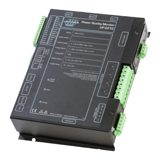
UNIPOWER UP-2210 Hardware installation and configuration manual Measuring device The measuring device UP-2210 is an advanced, 3-phase power quality and disturbance analyzer designed for permanent installation. Figure 2 Communication All measured data is automatically transferred from the meter to the server. There are several options for communication between the meters and the computer center. -
Page 10: Software
UNIPOWER UP-2210 Hardware installation and configuration manual Software The PQ Secure system consists mainly of four programs performing different functions. The system is built around a Microsoft SQL server, which stores all information about the system as well as the measure data. -
Page 11: Server Performance
Server performance 3.4.1 The required server performance depends on which PQ Secure application is being used. Unipower or our representatives can help you with choosing the right computer/server solution. Data growth in the database is approximate 0,35 to 0,9 GB per Meter per Month (MM) depending on configuration. -
Page 12: Installing Permanent Meter Up-2210
Note: If the meters are used with external/internal modem, keep in mind that phone lines are easily affected by lightning. Modems usually don’t have lightning protection. Unipower recommends that external lightning protection is installed between the phone line and modem in exposed locations, in order to protect the meter from damages caused by lightning. -
Page 13: Installation Diagram
UNIPOWER UP-2210 Hardware installation and configuration manual Installation diagram The UP-2210 meter can be mounted on the door or on the wall of the equipment cabinet. For mounting dimensions, refer to the drawing below. When mounting the meter, leave enough room at the side to prevent the contacts from getting jammed. - Page 14 UNIPOWER UP-2210 Hardware installation and configuration manual Figure 7 - side view Note: Make sure there is sufficient room to link all connectors. A minimum 20-30 mm is required. The display module connector needs 80mm clearance.
-
Page 15: Connection Points
UNIPOWER UP-2210 Hardware installation and configuration manual Connection points There are a number of connection points on the UP-2210 for connecting to the measured object and for communication links. The connections are described below: Figure 8 A. Digital outputs. Optional. The digital outputs are relays, which can be used for alarms and for controlling other equipment. - Page 16 If a suitable DC voltage source is available this is a preferred choice. If there is no station/internal battery backup, Unipower recommends that you connect the instrument to an external UPS type battery source in order to prevent power failure disturbances.
- Page 17 UNIPOWER UP-2210 Hardware installation and configuration manual I. UP-2210 meter has 3 isolated voltage inputs + reference (the range is stated on the front label). The voltage inputs are designed for the direct measurement of line-to-neutral voltages in low voltage networks as well as for connection to potential transformers (PT) secondary circuit in high voltage networks.
-
Page 18: Connection Alternatives
UNIPOWER UP-2210 Hardware installation and configuration manual Connection alternatives In the electric grid there are multiple configurations of instrument transformers (PT= Potential Transformer, CT= Current Transformer). The UP-2210 meters support all standard 1-phase and 3- phase connections. The meter is configured using PQ Online, where all the common connections methods with their respective wiring diagrams available and a graphical explanation. -
Page 19: 1-Phase Measurement With One Pt And One Ct
UNIPOWER UP-2210 Hardware installation and configuration manual 1-phase measurement with one PT and one CT 4.4.2 Figure 11 The above wiring diagram is used for single-phase measurement in public distribution networks with one CT and one PT. The voltage channel of the unit is connected to PT for measuring line-to-neutral voltage. -
Page 20: Hv 3-Phase Measurement With 2 Ct's And 2 Pt's (Line-To-Line Voltages)
UNIPOWER UP-2210 Hardware installation and configuration manual HV 3-phase measurement with 2 CT’s and 2 PT’s (Line-to-line voltages) 4.4.3 Figure 12 The above wiring diagram is used for three-phase measurement in public distribution networks with 2 CT´s and 2 PT’s. The voltage channels of the unit are connected to PT’s for measuring line-to-line. -
Page 21: Hv 3-Phase Measurement With 3 Ct's And 2 Pt's (Line-To-Line Voltages)
UNIPOWER UP-2210 Hardware installation and configuration manual HV 3-phase measurement with 3 CT’s and 2 PT’s (Line-to-line voltages) 4.4.4 Figure 13 The above wiring diagram is used for three-phase measurement in public distribution networks with 3 CT´s and 2 PT’s. The voltage channels of the unit are connected to PT’s (normally 110 V AC secondary), for supplying line-to-line voltages, and current channels are connected to CT’s (normally... -
Page 22: Hv 3-Phase Measurement With 2 Ct's And 3 Pt's (Line-To-Line Voltages)
UNIPOWER UP-2210 Hardware installation and configuration manual HV 3-phase measurement with 2 CT’s and 3 PT’s (Line-to-line voltages) 4.4.5 Figure 14 The above wiring diagram is used for three-phase measurement in in public distribution networks with 2 CT’s and 3 PT’s. The voltage channels of the unit are connected to the PT’s (normally 63 V AC secondary to earth), for supplying line-to-line voltages, and current channels are connected to the CT´s (normally 1 - 5 A AC secondary). -
Page 23: Hv 3-Phase Measurement With 3 Ct's And 3 Pt's (Line-To-Line Voltages)
UNIPOWER UP-2210 Hardware installation and configuration manual HV 3-phase measurement with 3 CT’s and 3 PT’s (Line-to-line voltages) 4.4.6 Figure 15 The above wiring diagram is used for three-phase measurement in public distribution networks with 3 CT´s and 3 PT’s. The voltage channels of the unit are connected to PT’s (normally 63 V AC secondary to earth), for supplying line-to-line voltages, and current channels are connected to CT´s... -
Page 24: 3-Phase Measurement With Direct Voltage, 2 Ct´s (Line-To-Neutral)
UNIPOWER UP-2210 Hardware installation and configuration manual 3-phase measurement with direct voltage, 2 CT´s (Line-to-neutral) 4.4.7 Figure 16 The above wiring diagram is used for 3-phase measurement in low voltage networks. The voltage channel of the unit is connected directly to the electricity network for measuring line-to-neutral voltage (230 V) and therefore do not require an instrument transformer (PT). -
Page 25: 3-Phase Measurement With Direct Voltage, 3 Ct´s And Neutral (Line-To-Neutral Voltages)
UNIPOWER UP-2210 Hardware installation and configuration manual 3-phase measurement with direct voltage, 3 CT´s and neutral (Line-to-neutral voltages) 4.4.8 Figure 17 The above wiring diagram is used for 3-phase measurement in low voltage networks. The voltage channel of the unit is connected directly to the electricity network for measuring line-to-neutral voltage (230 V) and therefore do not require an instrument transformer (PT). -
Page 26: 3-Phase 4 Wire Measurement With 2 Ct's And 2 Pt's
UNIPOWER UP-2210 Hardware installation and configuration manual 3-phase 4 wire measurement with 2 CT’s and 2 PT’s 4.4.9 Figure 18 The above wiring diagram is used for three-phase measurement in public distribution networks with 2 CT´s and 2 PT’s. The voltage channels of the unit are connected to PT’s (normally 63 V AC secondary to earth), for supplying line-to-line voltages, and current channels are connected to CT´s... -
Page 27: Phase With 4 Wire Measurement With 3 Ct's And 2 Pt's
UNIPOWER UP-2210 Hardware installation and configuration manual 3 phase with 4 wire measurement with 3 CT’s and 2 PT’s 4.4.10 Figure 19 The above wiring diagram is used for three-phase measurement in in public distribution networks with 3 CT´s and 2 PT’s. The voltage channels of the unit are connected to PT’s (normally 63 V AC secondary to earth), for supplying line-to-line voltages, and current channels are connected to CT´s... -
Page 28: Phase With 4 Wire Measurement With 2 Ct's And 3 Pt's
UNIPOWER UP-2210 Hardware installation and configuration manual 3 phase with 4 Wire measurement with 2 CT’s and 3 PT’s 4.4.11 Figure 20 The above wiring diagram is used for three-phase measurement in in public distribution networks with 2 CT´s and 3 PT’s. The voltage channels of the unit are connected to PT’s (normally 63 V AC secondary to earth), for supplying line-to-line voltages, and current channels are connected to CT´s... -
Page 29: Phase With 4 Wire Measurement With 3 Ct's And 3 Pt's
UNIPOWER UP-2210 Hardware installation and configuration manual 3 phase with 4 wire measurement with 3 CT’s and 3 PT’s 4.4.12 Figure 21 The above wiring diagram is used for three-phase measurement in public distribution networks with 3 CT´s and 3 PT’s. The voltage channels of the unit are connected to PT’s (normally 63 V AC secondary), for supplying line-to-earth voltages, and current channels are connected to CT´s... -
Page 30: Phase With 4 Wire Measurement With Direct Voltage And 2 Ct's
UNIPOWER UP-2210 Hardware installation and configuration manual 3 phase with 4 wire measurement with direct voltage and 2 CT’s 4.4.13 Figure 22 The above wiring diagram is used for 3-phase measurement in low voltage networks. The voltage channel of the unit is connected directly to the electricity network for measuring line-to-neutral voltage (230 V) and therefore do not require an instrument transformer (PT). -
Page 31: Phase With 4 Wire Measurement With Direct Voltage And 3 Ct's
UNIPOWER UP-2210 Hardware installation and configuration manual 3 phase with 4 wire measurement with direct voltage and 3 CT’s 4.4.14 Figure 23 The above wiring diagram is used for 3-phase measurement in low voltage networks. The voltage channel of the unit is connected directly to the electricity network for measuring line-to-neutral voltage (230 V) and therefore do not require an instrument transformer (PT). -
Page 32: Sp 2Ct 2Pt
UNIPOWER UP-2210 Hardware installation and configuration manual SP 2CT 2PT 4.4.15 Figure 24 The above wiring diagram is used for Channel: Measured object: Channel: Measured object: (Neutral) -
Page 33: Sp 2Ct Dv
UNIPOWER UP-2210 Hardware installation and configuration manual SP 2CT DV 4.4.16 Figure 25 The above wiring diagram is used for Channel: Measured object: Channel: Measured object: (Neutral) -
Page 34: Hv/Mv Earth Fault Monitoring Via Channel U4
UNIPOWER UP-2210 Hardware installation and configuration manual HV/MV Earth fault monitoring via channel U4 4.4.17 In high impedance grounded MV networks the voltage in the transformer’s ground point is of interest to study. Earth faults and emerging earth faults can be detected by analyzing the ground point voltage. -
Page 35: Vector Graph For Correct Connection
UNIPOWER UP-2210 Hardware installation and configuration manual Vector graph for correct connection To check and certify a correct connection of the measuring instrument you can use the program PQ Online. In PQ Online, under “Real time Analysis” a tab called “Vector”. This tool is a good controller to verify that you have plugged in phases correctly and turned the ammeters in the right direction. -
Page 36: Recommended Practices
UNIPOWER UP-2210 Hardware installation and configuration manual Recommended practices Below, recommendations are given for a number of common network situations. Impedance grounded 3-wire systems 4.6.1 Typical examples: MV distribution networks in a 3-phase, 3-wire network without neutral conductor impedance grounding (Petersen coil with/without resistor) is common. Figure 28 shows the secondary side of the transformer and the grounding impedance. -
Page 37: Isolated (Ungrounded) 3-Wire Systems
UNIPOWER UP-2210 Hardware installation and configuration manual Isolated (ungrounded) 3-wire systems 4.6.3 Typical examples: Industrial MV networks. In a 3-phase, 3-wire network without neutral conductor it is also common to isolate the network and leave it ungrounded. Connect your UP-2210 to measure line-line voltages U1-U3 and phase currents I1-I3 according to one of the sections 4.4.3, 4.4.4, 4.4.5 and 4.4.6 depending on how many PT/CT there are. -
Page 38: Connection Of Digital Inputs
UNIPOWER UP-2210 Hardware installation and configuration manual Connection of digital inputs 4.7.1 By connecting a signal voltage to the UP-2210’s digital inputs from external equipment (e.g. circuit breaker, harmonics filter), events can be registered and recordings can be triggered as a result of change in the digital signal. -
Page 39: Display Unit
5 seconds and re-insert the display cable at back of the display. The status LED of the UP2210 is also of great help to troubleshoot any problem with the display. As long as the status LED is Green the UP2210 is operating correctly. Should the status LED be red or not light at all this indicates a problem with the UP2210 and accordingly the display unit will not be operating as expected. -
Page 40: Installing Communication Equipment
This section covers the various options, including the brands recommended and sold by Unipower. The meter have standard interfaces and are not restricted to particular brands, but if you use other brands, please refer to the relevant user guides. - Page 41 UNIPOWER UP-2210 Hardware installation and configuration manual For successful communication, use right kind of cable for each equipment. Figure 31 It is important to lock the modem to the bit rate used by the meter. Figure 32 shows how the UP-2210 is connected to a phone modem:...
-
Page 42: Necessary Settings In The Modem
UNIPOWER UP-2210 Hardware installation and configuration manual Necessary settings in the modem 6.2.1 If the modem is connected directly to the meter no special settings are needed. The modem’s standard settings are used. The modem should in this case not be configured to answer automatically (ATS0=0). -
Page 43: Using Hyperterminal To Configure The Modem
UNIPOWER UP-2210 Hardware installation and configuration manual Using HyperTerminal to configure the modem 6.2.4 Start HyperTerminal, for example as follows: Start Programs Accessories Communication HyperTerminal A window opens, where you start by entering a name for your connection and then click on OK. In the next window, specify the COM port the modem is connected to (Not the modem type!). - Page 44 UNIPOWER UP-2210 Hardware installation and configuration manual Figure 35 When you have done this, enter the speed of the modem, remembering that the speed should be set to 57600 if the modem is connected directly to a meter (the speed of a GSM modem is usually set to 9600 or 19200 depending on the type of GSM modem), otherwise the speed is set depending on the requirements of the other equipment.
-
Page 45: Gsm Modem
UP-2210 Hardware installation and configuration manual GSM modem There are many GSM modems available, check with your Unipower representative for recommendations of units that work. You must carry out certain preparations before a GSM modem can be installed on site. You must first ensure that there is GSM coverage otherwise an additional antenna may be required. - Page 46 UNIPOWER UP-2210 Hardware installation and configuration manual Figure 37 shows how an UP-2210 is connected to a GSM modem: Figure 37 Article. Description. 22-9030 GSM modem 22-9080 Communications cable 9-pin/9-pin, 1.8m...
-
Page 47: Procedure
UNIPOWER UP-2210 Hardware installation and configuration manual Procedure 6.3.1 Brief summary of the procedure for activating the GSM modem: • Verify that the GSM subscription is activated for data traffic, and that the SIM card doesn’t have the PIN code activated, by installing the SIM card in a cell phone and turning on the phone. -
Page 48: Wireless Gsm/3G Router
A wireless GSM/3G router is a good way to access meters remotely via the existing wireless networks. There are many wireless routers available, check with your Unipower representative for recommendations of tested solutions that work. The protocol used depends on the wireless network (2G/3G) and technology the router uses. - Page 49 UNIPOWER UP-2210 Hardware installation and configuration manual Figure 39 shows two UP-2210s connected to a 3G router: Standard switch GPRS or 3G router Figure 39...
- Page 50 UNIPOWER UP-2210 Hardware installation and configuration manual RS-485 RS-485 is a serial communication that can be used together with some meters. It is similar to the common RS-232 but works with larger distances. Another advantage is that you can connect multiple meters to the same RS-485 cable (multi drop).
-
Page 51: Using Multiple Meters With Westermo Td-36 Pstn Modem And Rs-485
UNIPOWER UP-2210 Hardware installation and configuration manual Using multiple meters with Westermo TD-36 PSTN modem and RS-485 6.5.1 The Westermo TD-36 is an example of an industry PSTN (Public Switched Telephone Network) modem with both RS-485 and RS-232 connections. The RS-485 is an easy solution if you want to connect one or more meters to one modem/telephone line. - Page 52 UNIPOWER UP-2210 Hardware installation and configuration manual Start with setting all DIP switches in factory default mode: Then change according to the following pictures:...
- Page 53 UNIPOWER UP-2210 Hardware installation and configuration manual...
- Page 54 UNIPOWER UP-2210 Hardware installation and configuration manual Finish by restarting the modem.
-
Page 55: Settings In Up-2210
UNIPOWER UP-2210 Hardware installation and configuration manual Settings in UP-2210 6.5.1.1 When the equipment is connected you must change the communications settings in UP-2210. Use PQ Online to do this. Figure 42 Settings in the modem 6.5.1.2 Meters that use RS-485 don’t send commands to the modem to answer incoming calls (this is to avoid communications collisions). -
Page 56: Using Multiple Meters With Westermo Gdw-11 Gsm/Gprs-Modem And Rs-485
UNIPOWER UP-2210 Hardware installation and configuration manual Using multiple meters with Westermo GDW-11 GSM/GPRS-modem and RS-485 6.5.2 The Westermo GDW-11 is an example of an industry GSM/GPRS modem with both RS-485 and RS-232 connections. The RS-485 is an easy solution if you want to connect one or several meters to one wireless modem/SIM card. - Page 57 UNIPOWER UP-2210 Hardware installation and configuration manual...
- Page 58 UNIPOWER UP-2210 Hardware installation and configuration manual If you want to use the modem with RS-232 communication, change S1-4 from on to off. Power the modem off-on to make changes active.
-
Page 59: Settings In Up-2210
UNIPOWER UP-2210 Hardware installation and configuration manual Settings in UP-2210 6.5.2.1 When the equipment is connected you must change the communications settings in UP-2210. Use PQ Online to do this. Set baud rate to 9600 and select RS-232 or RS-485. -
Page 60: Configuring The Pentiline Pro
UNIPOWER UP-2210 Hardware installation and configuration manual Configuring the PentiLine PRO 6.6.1 The line divider is connected to the main jack, the touchtone telephone plugs into line 1, and lines 2- 5 are used for the meters (assumed to be modems). This arrangement is just one of the many configurations you can choose from. -
Page 61: Gps Clock Synchronisation Module
The GPS clock synchronization module can be used with the Unipower UP-2210. In order for the synchronization to work, the units must be equipped with the appropriate software as well as the necessary peripheral hardware. -
Page 62: Installation
The figures below shows the different GPS module and the GPS Adapter necessary for GPS installation. Connect the GPS to the Adapter and the adapter to the UP2210 through a straight UTP Patch cable. Check the adapter labels carefully! The GPS and the UP2210 must be connected to the specified port on the adapter, otherwise the communication will not work. -
Page 63: Gps Communication Configuration
GPS (default values are normally 4800, 9600 or 19200). Then press Apply. Figure 49 - GPS configuration This is all that Is needed to configure the UP2210 to use GPS synchronization. If everything is connected correctly and the GPS finds enough satellites, the “Sync” led on the UP2210 will start to flash rapidly (0.05s On and 0.9s Off). - Page 64 UNIPOWER UP-2210 Hardware installation and configuration manual Figure 50 - RTC sync information event The last digit indicates the source of time synchronization. “0” means PQ Schedule or manually by PQ Online. “1” means by GPS. If there is a communication error between the GPS and the meter there are several protective mechanisms in the software that prevent incorrect time from setting the meter.
-
Page 65: Installing Software
CD. The PQ Secure system is based on a database that supports a number of new methods of monitoring and analysis. Unipower personnel normally perform the installation, but the following description guides you if you want to do it yourself. Conduct the installation in the order described below. -
Page 66: Installing Pq Online
Browse button to open the file "Setup.exe" in the PQOnline\Disk1 folder, and click on OK. Installing UniLauncher 8.3.1 UniLauncher is a utility application that helps you to connect to your Unipower meters via USB. When you connect the USB cable UniLauncher will automatically connect with the meter and launch PQ Online. - Page 67 UNIPOWER UP-2210 Hardware installation and configuration manual The settings can be found under Properties: Figure 52 We recommend the above default settings. The path to the folder in Figure 52, A is the location where data will be automatically downloaded by UniLauncher.
-
Page 68: Pq Online
UNIPOWER UP-2210 Hardware installation and configuration manual PQ ONLINE PQ Online is mainly used for configuring the measuring devices UP-2210, Unilyzer 900/900C and Unilyzer 902, but is also used as a communication program between the measure site and the office. - Page 69 UNIPOWER UP-2210 Hardware installation and configuration manual SmartCom Server Here you specify the meters Serial number, Password and Host name. Figure 56 Select the appropriate alternative, and click the Connect button. The status window enables you to follow the communication process.
-
Page 70: Measurement Settings
UNIPOWER UP-2210 Hardware installation and configuration manual Measurement settings 8.4.2 Figure 57 In measurement setting you can view information about the actual settings, see Figure 57. Wire-connection configuration. Settings wizard, 8.4.2.1 You can use the settings wizard that guide you through the configuration of your meter. Press Setting wizard…button in Figure 57... - Page 71 UNIPOWER UP-2210 Hardware installation and configuration manual A. New setting When choosing new setting you will get four ways of selecting power transformer configuration as Figure 59 show. Select the actual configuration. Figure 59 Example below shows how to choose a four wire 3 phase configuration with 3 CT’s and 3 PT’s Select four-wire wye as instrument transformer configuration.
- Page 72 UNIPOWER UP-2210 Hardware installation and configuration manual Enter measurement transformer nominal level. Additional constants. Can be used for turning current reference by entering -1. Figure 61 In example above, Figure 61, the primary voltage is 11 kV and the secondary 110 V.
- Page 73 UNIPOWER UP-2210 Hardware installation and configuration manual Advanced settings are described in chapter 0 Figure 63 Press Next and enter Measure setting name and signature and press Finish to save the settings to the meter, see Figure 64 below. If you want to save the settings to a file choose Save to file…...
- Page 74 UNIPOWER UP-2210 Hardware installation and configuration manual B. Use the active setting. You can use the active settings and modify this and then save as a new configuration. Information about the actual highlighted parameter. Figure 65 In example above, Figure 65, the primary voltage is 11 kV and the secondary 110 V.
- Page 75 UNIPOWER UP-2210 Hardware installation and configuration manual Figure 67 Press Next and enter Measure setting name and signature and press Finish to save the settings to the meter, see Figure 68 below. If you want to save the settings to a file choose Save to file…...
-
Page 76: Advanced Settings
UNIPOWER UP-2210 Hardware installation and configuration manual Advanced settings 8.4.2.2 In advanced settings you have five overall setting icons. A. General settings B. Measure site properties C. Storage intervals D. Disturbance E. Slowscan settings These are described below. A. General settings... - Page 77 UNIPOWER UP-2210 Hardware installation and configuration manual B. Measure site properties Figure 70 In measure site settings you have several settings. You can also here highlight a row and get information about the setting and edit the value.
- Page 78 UNIPOWER UP-2210 Hardware installation and configuration manual C. Storage intervals Figure 71 In storage interval you set the intervals how often actual measurement unit will be stored. D. Disturbance Figure 72 In disturbances you set values for disturbances such as sags/swells and transients.
- Page 79 UNIPOWER UP-2210 Hardware installation and configuration manual Sags/Swells events The recorder can do a high-speed recording to allow detailed analysis of, for instance, a sag/swell event. The storage time is the total recording length and is set so that the event you want to capture is covered.
- Page 80 UNIPOWER UP-2210 Hardware installation and configuration manual Voltage triggers a) U1-U3 trigs at deviation [% Uref] A voltage sag (or swell) recording begins when the voltage one of the phases U1-U3 passes the Uref value +/- Figure 73 the trig level as in (1).
- Page 81 Since the resolution is lower a longer recording can be made. Maximum pre trig is 30 seconds and maximum recording length (including pre trig) is 300 seconds. For typical grid operations Unipower recommends a configuration of 10 seconds pre trig, 120 seconds post trig. Note that appropriate settings might take some trial and error before you find optimal storage length for your system.
- Page 82 UNIPOWER UP-2210 Hardware installation and configuration manual...
-
Page 83: Real-Time
UNIPOWER UP-2210 Hardware installation and configuration manual Real-time 8.4.3 Figure 75 PQ Online includes a real-time function allowing you to contact a meter in order to study the measured power quality parameters in real time. The dialogue contains two tabs A and B, each with a different way of presenting the information. - Page 84 UNIPOWER UP-2210 Hardware installation and configuration manual If you press the Oscilloscope tab B, following window appears. Figure 76 You can choose which parameters to be shown by selecting them G. If you for example want to set a specific colour of U1 then click on the arrow H. You will get a...
-
Page 85: Communication Settings
UNIPOWER UP-2210 Hardware installation and configuration manual Communication settings 8.4.4 Figure 77 In communication settings there are several settings tabs depending on communication type. A, Settings for Ethernet B, Settings for Serial ports C, Settings for Wi-Fi D, Settings for SmartCom... -
Page 86: Download Data
UNIPOWER UP-2210 Hardware installation and configuration manual Download data 8.4.5 Figure 78 In Download data window you can select the file to be downloaded. Pressing Custom Interval tab A gives you opportunities to specify an interval from the file that you will download data. -
Page 87: Tools
UNIPOWER UP-2210 Hardware installation and configuration manual Tools 8.4.6 Figure 79 In Tools there are four tabs. A, Status tab. In status tab you can see Date and time info for the meter, Hardware info and transducer info. You can set the time in meter to same time as in System by clicking on arrow E. -
Page 88: Language
UNIPOWER UP-2210 Hardware installation and configuration manual Language 8.4.7 Figure 80 In the startup window for PQ Online you can set language by clicking on the actual language A. Choose the language you want from the dropdown list. USB port 8.4.8... -
Page 89: Index
UNIPOWER UP-2210 Hardware installation and configuration manual Index GSM/GPRS modem ............. 56 100-BaseT ................40 10-BaseT ................16 HyperTerminal ..............43 HyperTerminal commands ........... 42 4-wire system ............... 37 Impedance grounded ............34, 36 Inputs ..................15 Installation ................ 5, 12 Installation diagram .............. - Page 90 UNIPOWER UP-2210 Hardware installation and configuration manual RJ-45 ..................40 Three phase ................20 RJ6/4 ..................59 Routing ................. 48 RS-232 ..............16, 56, 68 RS-485 ................. 56 UDP port ................48 RTC Sync ................63 UDP-port ................40 Undertaking ................6 Unilyzer 901 ................
Need help?
Do you have a question about the UP2210 and is the answer not in the manual?
Questions and answers