Table of Contents
Advertisement
Quick Links
Advertisement
Table of Contents

Subscribe to Our Youtube Channel
Summary of Contents for Wistron CA8-PRO
- Page 1 IEEE802.11 A/G Access Point User Guide V3, March 2008...
- Page 2 Copyright Statement No part of this publication may be reproduced, stored in a retrieval system, or transmitted in any form or by any means, whether electronic, mechanical, photocopying, recording or otherwise without the prior writing of the publisher. Windows ™ 95/98 and Windows ™ 2000 are trademarks of Microsoft ® Corp. Pentium is trademark of Intel.
- Page 3 Regulatory Information Federal Communication Commission Interference Statement This equipment has been tested and found to comply with the limits for a Class B digital device, pursuant to Part 15 of the FCC Rules. These limits are designed to provide reasonable protection against harmful interference in a residential installation. This equipment generates, uses and can radiate radio frequency energy and, if not installed and used in accordance with the instructions, may cause harmful interference to radio communications.
-
Page 4: Table Of Contents
Table of Contents Introduction ..............6 1.1 Overview ................6 1.2 Features ................7 1.3 Wireless Operation Modes ..........7 1.3.1 Access Point Mode ..............8 1.3.2 WDS Repeater Mode ............... 9 1.3.3 WDS Bridge Mode..............9 1.3.4 Client Infrastructure Mode ............10 1.3.5 Client Adhoc Mode .............. - Page 5 3.3.1 PASSWORD SETTINGS ............25 3.3.2 SYSTEM MANAGEMENT ............26 3.3.3 SNMP SETTINGS ..............27 3.3.4 MAC FILTERING SETTINGS ..........29 3.3.5 OPERATIONAL MODE............30 3.3.5 (1) Access Point Mode Settings..........30 -Wireless Settings................31 -SSID Settings................. 33 -QoS Settings .................. 34 -RADIUS Settings................
- Page 6 -Special Applications ............... 66 -IP Filtering Settings ................ 67 -IP Routing Settings................. 69 -Dynamic DNS Settings..............70 3.4 System Tools ..............71 3.4.1 Firmware Upgrade..............71 3.4.2 Configuration Save and Restore..........72 3.4.3 Factory Default ............... 72 3.4.4 Reboot System ............... 73 3.5 What if you forgot the password?........
-
Page 7: Introduction
Introduction 1.1 Overview The 802.11A/G ACCESS POINT is an access-point based on IEEE 802.11a/g based 2.4-GHz and 5-GHz radio technology. It contains an 802.11a/g and three half/full-duplex 10/100 LAN interfaces. The 802.11A/G ACCESS POINT features a total of 6 wireless modes: Access Point, WDS Repeater, WDS Bridge, Client Infrastructure, Client Adhoc and WISP Router. -
Page 8: Features
1.2 Features Compliant with 802.11a, 802.11b and 802.11g, Super A™ and Super G™ standards with roaming capability. Supports 6 wireless multi-function modes: Access Point, WDS Repeater, WDS Bridge, Client Infrastructure, Client Adhoc and WISP Router. Static assignment or DHCP client to set the device IP address. Multiple security measures: SSID hiding, Access Control List, WEP based encryption (64, 128, 152 bits), enhanced Security with 802.1x using a primary and a backup Radius Server with/without dynamic WEP keys,... -
Page 9: Access Point Mode
1.3.1 Access Point Mode When configured in the Access Point mode, the 802.11A/G ACCESS POINT allows a group of wireless stations to communicate with each other through it. Such a network is called an Infrastructure BSS. The 802.11A/G ACCESS POINT further provides bridging functions between the wireless network and the wired LAN network. -
Page 10: Wds Repeater Mode
1.3.2 WDS Repeater Mode In Repeater mode, the 802.11A/G ACCESS POINT set as a repeater extends the range of wireless LAN. The remote wireless AP/Router must also support WDS. Note that an 802.11A/G ACCESS POINT runs in the WDS Repeater mode can also support wireless stations simultaneously. -
Page 11: Client Infrastructure Mode
1.3.4 Client Infrastructure Mode In Client Infrastructure mode, the 802.11A/G ACCESS POINT is connected to a computer and acts like a wireless station, so that the computer can wirelessly access the other network’s services, such as Internet. Client Mode AP Mode User can access Internet Router... -
Page 12: Wisp Router Mode
1.3.6 WISP Router Mode In WISP Router Mode, 802.11A/G ACCESS POINT is connected to several computers and acts like a Client mode AP. With IP sharing function, the computers can share the WISP connection via 802.11A/G ACCESS POINT. Computer Computer Outdoor Client Router... -
Page 13: Static Ip
1.4.1 STATIC IP The default IP address of the LAN interface of an 802.11A/G ACCESS POINT is a private IP address of 192.168.1.1, and a network mask of 255.255.255.0. This means IP addresses of other devices on the LAN should be in the range of 192.168.1.2 to 192.168.1.254. -
Page 14: Install The 802.11 A/G Access Point
Install the 802.11 A/G Access Point This section describes the installation procedure for the 802.11A/G ACCESS POINT. It starts with a summary of the content of the package you have purchased, followed by steps of how to power up and connect the 802.11A/G ACCESS POINT. -
Page 15: Configuration Steps
You can reset the Access Point’s Settings to factory defaults by pushing a paperclip in the RESET hole. Push and hold until the lights at the front of the Access Point are off. 2.3 Configuration steps This section describes configuration required for the 802.11A/G ACCESS POINT before it can work properly in your network. -
Page 16: Set Up A Wireless Client As A Dhcp Client
POINT, the PC client may not be able to reach the ACCESS POINT. This is because they may no longer belong to the same IP network address space. Step 3. Change the setting of the PC back to “obtain IP addresses dynamically”. - Page 17 Otherwise, select Add to install it now. Step 4. In the new Network Component Type window, select Protocol. In the new Select Network Protocol window, select Microsoft in the Manufacturers area. Step 5. In the Network Protocols area of the same window, select TCP/IP, then click OK.
-
Page 18: Front Panel
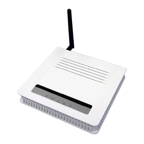
2.5 Front panel The LEDs on the front of the 802.11A/G ACCESS POINT reflect the operational status of the unit. The status of the LAN, the WLAN, and Power can be monitored from this display. POWER WLAN 802.11A/G Access Point LED Description Label WLAN POWER... -
Page 19: Basic Configuration
Basic Configuration This section describes the basic configuration procedure for the 802.11A/G ACCESS POINT. It describes how to set up the 802.11A/G ACCESS POINT for wireless connections, and the configuration of the local LAN environment. All basic configurations may be effected through a standard Web browser such as Microsoft Internet Explorer. -
Page 20: Setup Wizard
Log On If you attempt to access a configuration item from the browser menu, an administrator logon screen, shown below, will appear. If you are logging on for the first time, you should use the factory default setting “password”. The password is always displayed as a string of dots. Click the LOG ON button to start the configuration session. -
Page 21: Device Ip Settings
3.1.2 DEVICE IP SETTINGS The Device IP Settings screen allows you to configure the IP address and subnet of the device. Although you can rely on a DHCP server to assign an IP address to the 802.11A/G ACCESS POINT automatically, it is recommended that you configure a static IP address manually in most applications. -
Page 22: Wireless Settings
the DHCP client protocol to automatically get the IP address for this device”. Then click Next to go to the next screen. Again, as a reminder, it is recommended that your 802.11A/G ACCESS POINT should be assigned a static IP address in order to make it easy for you to manage the device later 3.1.3 WIRELESS SETTINGS Network ID (SSID): The SSID is the network name used to identify a wireless network. -
Page 23: Finish Setup Wizard And Save Your Settings
WLAN Mode: Select “11g/b”, “11g only”, “11b”, “11a”, “SuperG” or “SuperA”. The wireless module is IEEE 802.11g and 802.11b compliant, and choosing “11g/b” allows both 802.11b and 802.11g client stations to get associated. However, choosing “11g” allows only 802.11g client stations to get associated and get better overall performance. -
Page 24: System Log
3.2.1 SYSTEM LOG The 802.11A/G ACCESS POINT maintains a system log that you can use to track events that have occurred in the system. Such event messages can sometimes be helpful in determining the cause of a problem that you may have encountered. -
Page 25: Site Survey
Channel, Assoc. Tx Pkts, Rx Pkts and Error. 3.2.4 SITE SURVEY The Site Survey table shows the wireless Access Point and Adhoc stations in your environment detected by the 802.11 A/G Access Point. You can click the REFRESH button to get latest environment information. Site Survey list will indicate the following information: ESSID, MAC Address, Conn Mode, Channel, Turbo, Super, XR, WME, Signal strength (%), Security and Network... -
Page 26: Advanced Settings
3.3 Advanced Settings The advanced settings tab on the top row of the window allows you to perform modifications that normally you may not need to do for general operations except changing your password from the default factory setting (this is highly recommended for security purposes). -
Page 27: System Management
3.3.2 SYSTEM MANAGEMENT Clicking the System Management button to configure system related parameters to for the 802.11A/G ACCESS POINT. HTTP Port No.: HTTP stands for Hyper Text Transfer Protocol. The default port for the HTTP Web server is 80. Time-out: This setting specifies the duration of idle time (inactivity) before a web browser or telnet management session times out. -
Page 28: Snmp Settings
Syslog server IP address: System event messages generated by the wireless access point will be sent to a Syslog daemon running on a server identified by this IP address. 3.3.3 SNMP SETTINGS This screen allows you to configure SNMP parameters including the system name, the location and contact information. - Page 29 Community String For Read: If you intend the router to be managed from a remote SNMP management station, you need to configure a read-only “community string” for read-only operation. The community string is an alphanumeric string of up to 15 characters. Community String For Write: For read-write operation, you need to configure a write “community string”.
-
Page 30: Mac Filtering Settings
3.3.4 MAC FILTERING SETTINGS The 802.11A/G ACCESS POINT allows you to define a list of MAC addresses that are allowed or denied to access the wireless network. Disable MAC address control list: When selected, no MAC address filtering will be performed. Enable GRANT address control list: When selected, data traffic from only the specified devices in the table will be allowed in the network. -
Page 31: Operational Mode
3.3.5 OPERATIONAL MODE The 802.11A/G ACCESS POINT can be configured to operate in one of the following modes as mentioned previously in Chapter 1: (1) Access Point (2) WDS Repeater (3) WDS Bridge (4) Client Infrastructure (5) Client Adhoc (6) WISP Router (7) Gateway (AP-Router) 3.3.5 (1) Access Point Mode Settings Select “Access Point”... -
Page 32: Wireless Settings
-Wireless Settings Beacon Interval: The 802.11A/G ACCESS POINT broadcasts beacon frames regularly to announce its existence. The beacon Interval specifies how often beacon frames are transmitted in time unit of milliseconds. The default value is 100, and a valid value should be between 1 and 65,535. RTS Threshold: RTS/CTS frames are used to gain control of the medium for transmission. - Page 33 threshold must be transmitted following the RTS/CTS handshake exchange mechanism. The RTS threshold should have a value between 256-2347 bytes, with a default of 2347. It is recommended that this value does not deviate from the default too much. Fragmentation: When the size of a unicast frame exceeds the fragmentation threshold, it will be fragmented before the transmission.
-
Page 34: Ssid Settings
-SSID Settings SSID, a name for an access point (or a network), differentiates one WLAN from another. All devices in a same specific WLAN must use the same SSID. To Enable VLAN for all SSIDs, four SSID Name(s) can be set. Click the SSID name and VLAN ID, VLAN IP, VLAN NetMask, 802.1p priority (0:Best Effort;... -
Page 35: Qos Settings
-QoS Settings QoS stands for Quality of Service which attempts to provide different levels of quality to different types of network traffic. WMM stands for Wi-Fi Multimedia. WMM defines quality of service (QoS) in wireless networks. WMM improves audio, video and voice applications transmitted over wireless networks. -
Page 36: Radius Settings
-RADIUS Settings Radius servers provide centralized authentication services to wireless clients. Two Radius servers can be defined: one acts as a primary, and the other acts as a backup. MAC address filtering based authentication requires a MAC address filter table to be created in either the 802.11A/G ACCESS POINT (as described in Chapter 3.2.3 MAC Filtering Settings) and/or the Radius server. -
Page 37: 2) Wds Repeater Mode Settings
in Radius protocol messages. The shared secret configured in the 802.11A/G ACCESS POINT must match the shared secret configured in the RADIUS server. The shared secret can contain up to 64 alphanumeric characters. RADIUS Server Reattempt Period: The number of times the 802.11A/G ACCESS POINT should attempt to contact the primary server before giving up Enter the information for a second RADIUS server in case that there are 2 on your network which you are using authenticate wireless clients. -
Page 38: Wireless Settings
-Wireless Settings Beacon Interval: The 802.11A/G ACCESS POINT broadcasts beacon frames regularly to announce its existence. The beacon Interval specifies how often beacon frames are transmitted in time unit of milliseconds. The default value is 100, and a valid value should be between 1 and 65,535. RTS Threshold: RTS/CTS frames are used to gain control of the medium for transmission. - Page 39 threshold, it will be fragmented before the transmission. It should have a value of 256-2346 bytes, with a default of 2346. If you experience a high packet error rate, you should slightly decrease the Fragmentation Threshold. DTIM Interval: The 802.11A/G ACCESS POINT buffers packets for stations that operate in the power-saving mode.
-
Page 40: Qos Settings
-QoS Settings QoS stands for Quality of Service which attempts to provide different levels of quality to different types of network traffic. QoS stands for Quality of Service which attempts to provide different levels of quality to different types of network traffic. WMM stands for Wi-Fi Multimedia. -
Page 41: Radius Settings
-RADIUS Settings Radius servers provide centralized authentication services to wireless clients. Two Radius servers can be defined: one acts as a primary, and the other acts as a backup. MAC address filtering based authentication requires a MAC address filter table to be created in either the 802.11A/G ACCESS POINT (as described in Chapter 3.2.3 MAC Filtering Settings) and/or the Radius server. -
Page 42: 3) Wds Bridge Mode Settings
Radius Type: RADIUS Shared Secret: This is used by your RADIUS server in the Shared Secret field in Radius protocol messages. The shared secret configured in the 802.11A/G ACCESS POINT must match the shared secret configured in the RADIUS server. The shared secret can contain up to 64 alphanumeric characters. RADIUS Server Reattempt Period: The number of times the 802.11A/G ACCESS POINT should attempt to contact the primary server before giving up. -
Page 43: Wireless Settings
-Wireless Settings RTS Threshold: RTS/CTS frames are used to gain control of the medium for transmission. Any unicast (data or control) frames larger than specified RTS threshold must be transmitted following the RTS/CTS handshake exchange mechanism. The RTS threshold should have a value between 256-2347 bytes, with a default of 2347. -
Page 44: 4) Client Infrastructure Mode Settings
3.3.5 (4) Client Infrastructure Mode Settings Select “Client Infrastructure” mode and then click APPLY button. -Wireless Settings RTS Threshold: RTS/CTS frames are used to gain control of the medium for transmission. Any unicast (data or control) frames larger than specified RTS threshold must be transmitted following the RTS/CTS handshake exchange mechanism. -
Page 45: 5) Client Adhoc Mode Settings
with a default of 2347. It is recommended that this value does not deviate from the default too much. Fragmentation: When the size of a unicast frame exceeds the fragmentation threshold, it will be fragmented before the transmission. It should have a value of 256-2346 bytes, with a default of 2346. -
Page 46: Wireless Settings
-Wireless Settings Preamble: Select a preamble type. “Short and Long” or “Long Only”. RTS Threshold: RTS/CTS frames are used to gain control of the medium for transmission. Any unicast (data or control) frames larger than specified RTS threshold must be transmitted following the RTS/CTS handshake exchange mechanism. -
Page 47: 6) Wisp Router Mode Settings
3.3.5 (6) WISP Router Mode Settings Select “WISP Router” mode and then click APPLY button. -Wireless Settings RTS Threshold: RTS/CTS frames are used to gain control of the medium for transmission. Any unicast (data or control) frames larger than specified RTS threshold must be transmitted following the RTS/CTS handshake exchange mechanism. -
Page 48: Dhcp Server Settings
with a default of 2347. It is recommended that this value does not deviate from the default too much. Fragmentation: When the size of a unicast frame exceeds the fragmentation threshold, it will be fragmented before the transmission. It should have a value of 256-2346 bytes, with a default of 2346. -
Page 49: Multiple Dmz
Select the check box of “Enable DHCP Server” to enable DHCP server function. The range of Clients’ IP addresses is from 192.168.1.2 to 192.168.1.254. You can assign an IP address to a specified MAC address. -Multiple DMZ Select a DMZ type and then enter the local DMZ IP address. Note: A DMZ server is a common term used to describe the default virtual server. -
Page 50: Virtual Server Settings
-Virtual Server Settings This allows you to specify one or more applications running on server computers on the LAN that may be accessed by any Internet user. Internet data destined for the specified public port will be directed to the specified private port number on the LAN client with the specified private IP address. -
Page 51: Special Applications
-Special Applications Some Internet application such as Instant Messaging or Games in particular use groups of ports, and are not easy to work behind a firewall. To work well with these special applications we will open ports to let traffic pass through. Note: You can use up to 3 sets of opened ports for a specific application. -
Page 52: Ip Filtering Settings
-IP Filtering Settings IP filtering is simply a mechanism that decides which types of IP datagrams will be processed normally and which will be discarded. This allows you to define rules for allowing / denying access from / to the Internet. - Page 53 Deny IP access: Data traffic satisfying rules below are denied/filtered. You can also define IP filtering rule, such as: Name; IP Protocol; Apply to either Outbound to the Internet or Inbound from the Internet; Source IP Address and Dest. (Destination) IP Address. To grant or deny IP address, select ADD or Delete Selected.
-
Page 54: Ip Routing Settings
-IP Routing Settings Dynamic Routing: Select the routing protocol scheme used for the router’s LAN / WAN port. -
Page 55: Dynamic Dns Settings
Static Routing: This allows you to manually configure static network routes. Static routes will override routes learned by standard routing protocol discover methods. IP Routing Table: To delete a static route from the table, select the route and click DELETE SELECTED. -
Page 56: 7) Gateway (Ap-Router) Mode Settings
3.3.5 (7) Gateway (AP-Router) Mode Settings Select “Gateway (AP+Router)” mode and then click APPLY button. -ISP Settings For configuring ISP settings, go to Setup Wizard and click ISP Settings from menu bar. Please note that the ISP Settings page can be browsed only when the computer is connected wirelessly to 802.11A/G ACCESS POINT. - Page 57 Click SET PRIMARY to set the selected ISP as the primary ISP. The current connection will be highlighted in light green. For the ISP configuration, get information from your ISP. Enter an ISP Name and then decide which of the following methods to use to set up Internet connection: Static IP, PPPoE, DHCP, or PPTP.
- Page 58 Cloned MAC Address: If your ISP requires you to use a specific WAN Ethernet MAC address for identification purposes, check this box and enter the MAC address. After setting up the connection, click ADD to add it to the ISP table. Go back to Advanced Settings for further configurations.
-
Page 59: Wireless Settings
-Wireless Settings Beacon Interval: The 802.11A/G ACCESS POINT broadcasts beacon frames regularly to announce its existence. The beacon Interval specifies how often beacon frames are transmitted in time unit of milliseconds. The default value is 100, and a valid value should be between 1 and 65,535. RTS Threshold: RTS/CTS frames are used to gain control of the medium for transmission. - Page 60 threshold must be transmitted following the RTS/CTS handshake exchange mechanism. The RTS threshold should have a value between 256-2347 bytes, with a default of 2347. It is recommended that this value does not deviate from the default too much. Fragmentation: When the size of a unicast frame exceeds the fragmentation threshold, it will be fragmented before the transmission.
-
Page 61: Ssid Settings
-SSID Settings SSID, a name for an access point (or a network), differentiates one WLAN from another. All devices in a same specific WLAN must use the same SSID. To Enable VLAN for all SSIDs, four SSID Name(s) can be set. Click the SSID name and VLAN ID, VLAN IP, VLAN NetMask, 802.1p priority (0:Best Effort;... -
Page 62: Qos Settings
-QoS Settings QoS stands for Quality of Service which attempts to provide different levels of quality to different types of network traffic. WMM stands for Wi-Fi Multimedia. WMM defines quality of service (QoS) in wireless networks. WMM improves audio, video and voice applications transmitted over wireless networks. -
Page 63: Radius Settings
-RADIUS Settings Radius servers provide centralized authentication services to wireless clients. Two Radius servers can be defined: one acts as a primary, and the other acts as a backup. MAC address filtering based authentication requires a MAC address filter table to be created in either the 802.11A/G ACCESS POINT (as described in Chapter 3.2.3 MAC Filtering Settings) and/or the Radius server. -
Page 64: Dhcp Server Settings
in Radius protocol messages. The shared secret configured in the 802.11A/G ACCESS POINT must match the shared secret configured in the RADIUS server. The shared secret can contain up to 64 alphanumeric characters. RADIUS Server Reattempt Period: The number of times the 802.11A/G ACCESS POINT should attempt to contact the primary server before giving up Enter the information for a second RADIUS server in case that there are 2 on your network which you are using authenticate wireless clients. -
Page 65: Multiple Dmz
-Multiple DMZ Select a DMZ type and then enter the local DMZ IP address. Note: A DMZ server is a common term used to describe the default virtual server. If the DMZ server is selected, Internet traffic not destined for a valid virtual server is redirected to this privately addressed LAN client. -
Page 66: Virtual Server Settings
-Virtual Server Settings This allows you to specify one or more applications running on server computers on the LAN that may be accessed by any Internet user. Internet data destined for the specified public port will be directed to the specified private port number on the LAN client with the specified private IP address. -
Page 67: Special Applications
-Special Applications Some Internet application such as Instant Messaging or Games in particular use groups of ports, and are not easy to work behind a firewall. To work well with these special applications we will open ports to let traffic pass through. Note: You can use up to 3 sets of opened ports for a specific application. -
Page 68: Ip Filtering Settings
-IP Filtering Settings IP filtering is simply a mechanism that decides which types of IP datagrams will be processed normally and which will be discarded. This allows you to define rules for allowing / denying access from / to the Internet. - Page 69 Deny IP access: Data traffic satisfying rules below are denied/filtered. You can also define IP filtering rule, such as: Name; IP Protocol; Apply to either Outbound to the Internet or Inbound from the Internet; Source IP Address and Dest. (Destination) IP Address. To grant or deny IP address, select ADD or Delete Selected.
-
Page 70: Ip Routing Settings
-IP Routing Settings Dynamic Routing: Select the routing protocol scheme used for the router’s LAN / WAN port. -
Page 71: Dynamic Dns Settings
Static Routing: This allows you to manually configure static network routes. Static routes will override routes learned by standard routing protocol discover methods. IP Routing Table: To delete a static route from the table, select the route and click DELETE SELECTED. -
Page 72: System Tools
3.4 System Tools 3.4.1 Firmware Upgrade You can upgrade the firmware of your 802.11A/G ACCESS POINT (the software that controls your 802.11A/G ACCESS POINT’s operation). Normally, this is done when a new version of firmware offers new features that you want, or solves problems that you have encountered with the current version. -
Page 73: Configuration Save And Restore
3.4.2 Configuration Save and Restore You can save system configuration settings to a file, and later download it back to the 802.11A/G ACCESS POINT by following the steps. Step 1. Select from the System Tools menu. Step 2. Enter the path of the configuration file to save-to/restore-from (or click the Browse button to locate the configuration file). -
Page 74: Reboot System
3.4.4 Reboot System You can reset your 802.11A/G ACCESS POINT from the Browser. To reset it: Step 1. Select Reboot System from the System Tools menu. Step 2. Click YES to reboot the 802.11A/G ACCESS POINT. Rebooting the 802.11A/G ACCESS POINT disconnects any active clients, and therefore will disrupt any current data traffic. -
Page 75: What If You Forgot The Password
3.5 What if you forgot the password? If you forgot the password, the only way to recover is to clear the device configuration and return the unit to its original state as shipped from the factory. You can reset the Access Point’s Settings to factory defaults by pushing a paperclip in the RESET hole on the back panel. -
Page 76: Specifications
Specifications Product Name IEEE 802.11a/g Access Point Linux® 2.4.18 • IEEE 802.11a/b/g • IEEE 802.1d Spanning Tree Standard • IEEE 802.1x • IEEE 802.3u Ethernet protocol • Infrastructure WLAN Network Architecture Type Wireless Transfer Data Rate for IEEE 802.11a Standard: 54, 48, 36, 24, 18, 12, 9 &... - Page 77 • DHCP Client IP Address Assignment • Static IP Address • Operation Temperature: 0 • Storage Temperature: -20 ~ 65 Environmental Specification • Operating Humidity: 10% ~90% (without Condensation) EMC Certification • CE...
Need help?
Do you have a question about the CA8-PRO and is the answer not in the manual?
Questions and answers