Advertisement
Quick Links
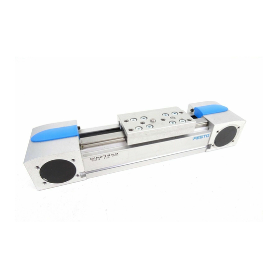
EGC-TB, EGC-HD-TB
Toothed belt axis
Instructions | Operating
8110938
201906d
[8110940]
Translation of the original instructions
1
Further applicable documents
All available documents for the product è www.festo.com/pk.
2
Safety
2.1
Safety instructions
–
Observe labelling on the product.
–
Prior to assembly, installation and maintenance work: Switch off power sup
ply, ensure that it is off and secure it against being switched back on.
–
Store the product in a cool, dry, UVprotected and corrosionprotected envir
onment. Ensure that storage times are kept to a minimum.
–
Observe tightening torques. Unless otherwise specified, the tolerance
is ± 20 %.
2.2
Intended use
The axis is intended to be used for positioning payloads in combination with tools
or as a drive when external guides are used.
The axis is only approved for slide operation.
Fig. 1 Slide operation
2.3
Training of qualified personnel
Installation, commissioning, maintenance and disassembly should only be con
ducted by qualified personnel. The qualified personnel must be familiar with
installation of electrical control systems.
3
Further information
–
Accessories è www.festo.com/catalogue.
–
Spare parts è www.festo.com/spareparts.
4
Service
Contact your regional Festo contact person if you have technical questions
è www.festo.com.
5
Product overview
5.1
Function
The axis converts the rotary motion of the mounted motor into a linear motion of
the slide. The torque of the motor is transmitted to the slide by the toothed belt
drive (TB). The linear movement of the slide is precisely guided by the guide.
Sensors and displacement measuring system enable the monitoring of end posi
tions, reference position and intermediate position.
5.2
Product design EGC-TB
Festo SE & Co. KG
Ruiter Straße 82
73734 Esslingen
Germany
+49 711 3470
www.festo.com
8110938
1 Drive hollow shaft
2 Threaded hole for motor mounting
kit
3 Drive cover
4 Guide rail
5 Toothed belt
6 Guide lubrication point
7 Threaded and centring hole for
attachment component
8 Threaded hole for switch lug
Fig. 2 Product design EGCTB
Product design EGC-HD-...-TB
1 Drive hollow shaft
2 Threaded hole for motor mounting
kit
3 Drive cover
4 Guide rail
5 Toothed belt
6 Guide lubrication point
7 Threaded and centring hole for
attachment component
Fig. 3 Product design EGCHD...TB
6
NOTICE!
Unexpected and unbraked movement of components
•
Secure moving components for transport.
Transport and storage conditions
1. Take product weight into account è 14 Technical data.
Weight > 25 kg: Transport with a suitable hoist (crossbrace) or with two per
sons.
2. Consider axis centre of gravity.
3. Comply with maximum permitted support clearances when attaching trans
portation aids è 14.2 Characteristic curves.
4. Store and transport the product in its original packaging.
Product design
Transport and storage
9 Slide
10 Cover cap
11 Shaft cover
12 Slot for sensor
13 Slot for profile mounting, slot nut
and sensor bracket
14 Slot for slot nut
15 Profile
16 Threaded hole for foot mounting
8 Threaded hole for switch lug
9 Slide
10 Cover cap
11 Shaft cover
12 Slot for sensor
13 Slot for profile mounting, slot nut
and sensor bracket
14 Slot for slot nut
15 Profile
Advertisement

Related Manuals for Festo EGC-50-TB


Summary of Contents for Festo EGC-50-TB
- Page 1 9 Slide 10 Cover cap Service 3 Drive cover 11 Shaft cover Contact your regional Festo contact person if you have technical questions 4 Guide rail è www.festo.com. 12 Slot for sensor 5 Toothed belt 13 Slot for profile mounting, slot nut...
- Page 2 Collision free Evenness Centre of mass Max. screw-in 2. Fasten motor mounting kit, observe instructions è www.festo.com/sp. and tilting depth 3. Fasten the motor without tension. Support large and heavy motors. moment Connect motor cables only on completion of mounting.
-
Page 3: Operation
– Prevention of contamination in the slots. – Control and homing travel at reduced velocity, acceleration and deceleration 1. Select accessories è www.festo.com/catalogue. setpoints. 2. Mount mechanical end position protection: – No test run to mechanical end stops. - Page 4 – 120: 1.2 g – 185: 3.6 g – Periodic check: every 1000 km. EGCHD...TB (size) 2. If there is visible wear on the toothed belt: Send the axis to Festo or contact – 125: 1 g è www.festo.comFesto Service. – 160: 1.1 g – 220: 2.7 g 10.3...
- Page 5 Reduce travel velocity. Tab. 10 Overview Fault clearance 11.2 Repair – Observe the instructions for dismantling è 12 Disassembly – Send axis to Festo repair service. – Information about spare parts and accessories è www.festo.com/spareparts. Tab. 11 General data, EGCTB, EGCHD...TB Disassembly EGC-TB EGC-HD-...-TB...
- Page 6 Theoretical feed force F as a function of the input torque M – Max. acceleration a as a function of the payload m 1000 2000 3000 4000 5000 6000 Diagrams è www.festo.com/catalogue. L [mm] EGCHD125TB EGCHD220TB EGCHD160TB Fig. 7 Support distances L as a function of force Fy...
Need help?
Do you have a question about the EGC-50-TB and is the answer not in the manual?
Questions and answers