
Related Manuals for Emerson Net Safety MLP-A-SC1100


Summary of Contents for Emerson Net Safety MLP-A-SC1100
- Page 1 Number: MAN-0047 Rev 16 January 2017 Net Safety™ Millennium Combustible Gas Detector User Manual Models: MLP-A/AR/AD-SC1100 MLP-LP-A/AR/ARS-SC1100...
- Page 3 Important Information The contents of this publication are presented for informational purposes only, and while every effort has been made to ensure their accuracy, they are not to be construed as warranties or guarantees, expressed or implied, regarding the products or services described herein or their use or applicability.
- Page 4 Warranty Limited Warranty. Subject to the limitations contained in Section 10 (Limitation of Remedy and Liability) herein, Seller warrants that (a) the licensed firmware embodied in the Goods will execute the programming instructions provided by Seller; (b) that the Goods manufactured by Seller will be free from defects in materials or workmanship under normal use and care;...
-
Page 5: Table Of Contents
Operations Manual Table of Contents FGD-MAN-0047 January 2017 Contents Section 1: Introduction ......................The sensor ..................................1 The controller (transmitter) ............................1 The manual ..................................1 Section 2: Plan ........................Locate controller / sensor ............................... 3 Option 1 ..................................3 Option 2 .................................. - Page 6 Table of Contents Operations Manual January 2017 FGD-MAN-0047 Section 6: The main menu ....................Accessing the main menu ............................. 17 Main menu functionality ............................... 17 Section 7: Calibrate ......................Calibration procedure ..............................19 Steps in calibration procedure ............................20 Remote calibration ............................... 20 7.3.1 Abort calibration .............................
- Page 7 Operations Manual Table of Contents FGD-MAN-0047 January 2017 Section 9: Maintain ......................Periodic response check ............................... 29 Troubleshoot ................................29 Troubleshooting guide ..............................30 Section 10: How to return equipment ................10.1 Spare parts/accessories ..............................32 10.2 Face rotation option ..............................33 10.2.1 Rotate PCB assembly ............................
- Page 8 List of Tables Operations Manual January 2017 FGD-MAN-0047 List of Tables Table 4-1 Sensor terminal connection ............................8 Table 4-2 Controller terminal connection ........................... 9 Table 5-1 Status LEDs, Display messages, and current loop ....................... 14 Table 5-2 RTU Status register (40002) Read only (binary) ......................14 Table 8-1 Default relay settings ..............................
- Page 9 Operations Manual List of Figures FGD-MAN-0047 January 2017 List of Figures Figure 2-1 Locate sensor/controller - separated ........................... 3 Figure 2-2 Dimensional drawing ..............................4 Figure 3-1 Components ................................5 Figure 4-1 Securing wires ................................7 Figure 4-2 Millennium module boards ............................8 Figure 4-3 Wiring - controller and sensor............................
-
Page 11: Section 1: Introduction
Operations Manual FGD-MAN-0047 January 2017 Section 1: Introduction The manual The manual has been designed to make installation of the Millennium The Millennium series is a part of Net Safety's innovation in a line of product easy. To ensure proper installation, follow the steps outlined in continuously evolving industrial gas detectors and sensors. - Page 12 Operations Manual January 2017 FGD-MAN-0047...
-
Page 13: Section 2: Plan
Operations Manual FGD-MAN-0047 January 2017 Section 2: Plan the sensor. Tubing can be run from the CCS-1 to a convenient location accessible for calibration gas to be injected. Option 2 Locate controller / sensor The sensor is attached directly to the controller. See Figure 2-1 Prior to the installation process, a location plan for placing the details. -
Page 14: Figure 2-2 Dimensional Drawing
Operations Manual January 2017 FGD-MAN-0047 Figure 2-2 below shows the controller with sensor and the multi- purpose junction box with sensor attached. Figure 2-2 Dimensional drawing CCS-1 Controller with sensor Multi-purpose junction box with sensor... -
Page 15: Section 3: Install
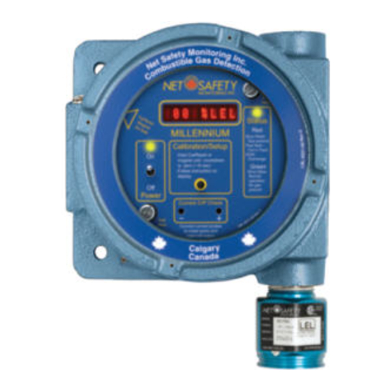
If you find any components missing or damaged, notify the representative or Emerson immediately. Figure 3-1 Components Controller base housing Millennium faceplate... -
Page 16: External Equipment
Operations Manual January 2017 FGD-MAN-0047 External equipment It is necessary that reliable monitoring and indicating devices or systems be connected to the detector. These devices must be designed to produce clear visual and audible danger signals when high signal levels occur. Mount The controller should be mounted near eye-level and be easily accessible for calibration and maintenance purposes. -
Page 17: Section 4: Wire
Operations Manual FGD-MAN-0047 January 2017 Section 4: Wire Explosion-proof installations may require an additional seal where conduit enters a non-hazardous area. Ensure conformity with local wiring codes. Field installation When pouring a seal, use a fiber dam to ensure proper formation of the seal. -
Page 18: Board Assembly
Operations Manual January 2017 FGD-MAN-0047 Board assembly Sensor and controller There are three different user-allowed removable boards: relay board (solid state or electromechanical), option board, and Modbus board. These boards are field replaceable. Simply loosen the locking standoffs, Power to the unit must be OFF before wiring. remove one board, insert the other board, and tighten screws. -
Page 19: Relay Board
Operations Manual FGD-MAN-0047 January 2017 Table 4-2 Controller terminal connection 4.4.2 RS-485 communication Connect devices in a chain via the Modbus terminals. The last device in Controller Power connections the chain requires end of line termination. Refer to Modbus (terminal board) termination. -
Page 20: Non-Isolated And Isolated Power Configurations
Operations Manual January 2017 FGD-MAN-0047 For Isolated configuration using a separate power supply to isolate the current loop, the jumper must be placed over Pin 1 and Pin 2 for source Unless otherwise specified, all models ship with this jumper in the non- and sink. -
Page 21: Modbus Termination
Operations Manual FGD-MAN-0047 January 2017 Figure 4-6 Remote reset Modbus termination Devices can be networked in a daisy chain. The device located at the end of the chain requires end of line termination. Place both jumpers over the pins as shown in the Figure 4-7 below. - Page 22 Operations Manual January 2017 FGD-MAN-0047...
-
Page 23: Section 5: Operate
Operations Manual FGD-MAN-0047 January 2017 Section 5: Operate Figure 5-1 Controller functionality... -
Page 24: Table 5-1 Status Leds, Display Messages, And Current Loop
Operations Manual January 2017 FGD-MAN-0047 Table 5-1 Status LEDs, Display messages, and current loop Table 5-2 RTU Status register (40002) Read only (binary) Current Status LED State Display output red or green RTU Status registers and meaning Calibrate sensor 3.0 mA RTUstat_fault 0x0001 Fault(sensor) -
Page 25: Calibration Button
Operations Manual FGD-MAN-0047 January 2017 Calibration button Power up The Calibration button provides access to the Millennium’s main menu, Turn the power switch on. A 90 second warm-up routine will begin. The which in turn allows calibration and options to be reviewed and set. display reads Start Delay Millennium Net Safety, the Status LED flashes Refer to Figure 5-1 Controller functionality... - Page 26 Operations Manual January 2017 FGD-MAN-0047...
-
Page 27: Section 6: The Main Menu
Operations Manual FGD-MAN-0047 January 2017 Section 6: The main menu If you do not wish to select that option, wait until the next option appears and then select YES?. The main menu provides access to various functional settings and ... - Page 28 Operations Manual January 2017 FGD-MAN-0047...
-
Page 29: Section 7: Calibrate
Operations Manual FGD-MAN-0047 January 2017 Section 7: Calibrate Calibration procedure The calibration procedure requires about five minutes to complete. If gas is not applied at the appropriate time, a calibration failure may occur. Refer to Calibration failure for specific information. For accurate performance, the Millennium should be calibrated using 50% span of the specific gas of concern. -
Page 30: Steps In Calibration Procedure
Always use 1.0 liter per minute for distances every two seconds; no fault indicated. (calibration tube lengths) between10 ft. and 100 ft. Contact Emerson if 2. Flow certified clean air at a rate of 0.5 liters per minute through a remote calibration distance is greater than 100 ft/30 m is required. -
Page 31: Calibration Failure
Operations Manual FGD-MAN-0047 January 2017 7.4.2 Calibration failure If the calibration procedure fails, the display shows Fail Cal, the Status LED alternates red/green flashes and the analog output changes back and forth from 3.0–3.3 mA. The unit remains in a failed state until a Manual reset. - Page 32 Operations Manual January 2017 FGD-MAN-0047...
-
Page 33: Section 8: Monitor
Operations Manual FGD-MAN-0047 January 2017 Section 8: Monitor Table 8-1 Default relay settings Millennium Alarm levels Coil Status Review relay settings model # High Fault This is a read-only mode; changes cannot be made. 1. Press and hold the Calibration button or hold the magnet to the reed switch to enter the main menu;... -
Page 34: Enter Restricted Menu
Operations Manual January 2017 FGD-MAN-0047 8.3.1 Extend sensor separation 3. The message Coil Status displays. The display then shows Energized YES? and then De-Energized YES?. 1. Enter the Restricted menu. Refer to Enter Restricted menu. 4. Press the Calibration button or use the reed switch to select. The 2. -
Page 35: Select Display Language
Operations Manual FGD-MAN-0047 January 2017 Brightness YES? displays, then select. 4. Use the Calibration button or use the reed switch to select each of The flashing YES confirms the selection. three numbers in the new address: 3. When Disable 4 - 20mA O/P YES? displays, press the Calibration - select the last number in the address first: 0 thru 9. -
Page 36: Sensor Drift
Operations Manual January 2017 FGD-MAN-0047 detected, the Status LED flashes slow red, the display shows Sensor 8.7.1 Bump testing Fault, and the analog output changes to 2.5 mA. As part of the site preventative maintenance program, and to ensure the sensor has not been poisoned, Net Safety recommends that a 8.4.2 Sensor drift bump test of the sensor is completed every three (3) months or It is a normal characteristic of gas sensors to exhibit a slow drift from... -
Page 37: Reset
Operations Manual FGD-MAN-0047 January 2017 SensorGuard includes a unique safety feature where high alarm relays normally open and normally closed contacts available at the output and the analog output latch when 60% LEL is exceeded. SensorGuard terminals. includes an analog ratchet so that LEL values above 60% are recorded The Fault relay is set for normally energized operation and is non- and latched until reset manually. - Page 38 Operations Manual January 2017 FGD-MAN-0047...
-
Page 39: Section 9: Maintain
Operations Manual FGD-MAN-0047 January 2017 Section 9: Maintain Troubleshoot Response to the input should be checked and, if necessary, calibration Periodic response check should be performed whenever any of the following occur. Refer to Calibration procedure for calibration instructions. We recommend the Millennium be verified or calibrated every ... -
Page 40: Troubleshooting Guide
Operations Manual January 2017 FGD-MAN-0047 Troubleshooting guide Table 9-1 Troubleshooting guide Condition Possible cause Possible solution Faulty power supply or wiring. Correct power supply or wiring. Intermittent power Voltage is below operational voltage. Correct input voltage to unit. Failed electronic component(s). Contact factory. - Page 41 Operations Manual FGD-MAN-0047 January 2017 Condition Possible cause Possible solution Incorrect relay settings in menu. Correct relay settings in menu. Undesirable change in relay state Voltage applied to relay contacts outside relay ratings. Correct voltage applied to relay dry contacts. See Appendix C: Sensor specifications for specifications.
-
Page 42: Section 10: How To Return Equipment
A Material Return Authorization number is required in order to return equipment. Contact Emerson at +1 866 347 3427 before returning Pack items to protect them from damage and use anti-static bags or equipment or consult our Service Department to possibly avoid aluminium-backed cardboard as protection from electrostatic returning equipment. -
Page 43: Face Rotation Option
Operations Manual FGD-MAN-0047 January 2017 Net Safety part 2. Turn the power to the detector off. Description number 3. Unscrew both the knobs marked Pull Here. Solid State Relay Board 4. Lift controller faceplate from housing and allow to hang from ribbon ML7-ORS303 (ML7-RS303 c./w Option Board(ML7-OP100) cable. -
Page 44: Figure 10-2 Pcb Assembly Rotated
Operations Manual January 2017 FGD-MAN-0047 Figure 10-2 PCB assembly rotated for handling Appendix A: Electrostatic sensitive device (ESD) electronic components. - Page 45 Operations Manual FGD-MAN-0047 January 2017...
-
Page 46: Appendix A: Electrostatic Sensitive Device (Esd)
Operations Manual January 2017 FGD-MAN-0047 Ensure ALL personnel are educated and trained in ESD Control Procedures. Appendix A: Electrostatic In general, exercise accepted and proven precautions normally observed when handling electrostatic sensitive devices. sensitive device (ESD) A warning label is placed on the packaging, identifying products using Electrostatic discharge (ESD) is the transfer, between bodies, of an electrostatic sensitive semiconductor devices. - Page 47 Operations Manual FGD-MAN-0047 January 2017...
-
Page 48: Appendix B: Resistance Table
Operations Manual January 2017 FGD-MAN-0047 Appendix B: Resistance table Table B-1: Resistance table Distance (feet) AWG #20 AWG #18 AWG #16 AWG #14 AWG #12 AWG #10 AWG #8 1.02 0.64 0.40 0.25 0.16 0.10 0.06 2.03 1.28 0.80 0.51 0.32 0.20 0.13... - Page 49 Operations Manual FGD-MAN-0047 January 2017 Distance (feet) AWG #20 AWG #18 AWG #16 AWG #14 AWG #12 AWG #10 AWG #8 6500 66.00 41.50 26.10 16.40 10.30 6.50 4.08 7000 71.10 44.70 28.10 17.70 11.10 7.00 4.40 7500 76.10 47.90 30.10 19.00 12.00...
-
Page 50: Appendix C: Sensor Specifications
Operations Manual January 2017 FGD-MAN-0047 Appendix C: Sensor specifications Table C-1 Millennium sensor specifications Operating temperature range -40 °F to 185 °F (-40 °C to 85 °C) Weight 0.2 lb. (0.1 kg) Enclosure material Powder coated or anodized aluminum (optional stainless steel) Range of detection 0 to 100% LEL of most hydrocarbons and hydrogen Accuracy... - Page 51 Operations Manual FGD-MAN-0047 January 2017...
-
Page 52: Appendix D: Controller Specifications
Operations Manual January 2017 FGD-MAN-0047 Appendix D: Controller specifications Table D-1: Millennium Controller specifications Low power board Low power board 4–20 mA analog 4-20 mA analog and RS-485 Modbus 4–20 mA analog 4–20 mA with relay output (disabled) Millennium relay output (solid RTU digital output output module... - Page 53 Notes...
- Page 54 Notes...
- Page 56 The Emerson logo is a trademark and service mark of Emerson Electric Co. Safety.CSC@Emerson.com Net Safety is a trademark of one of the Emerson Process Management family of companies. All other marks are the property of their respective owners. Asia Pacific...
Need help?
Do you have a question about the Net Safety MLP-A-SC1100 and is the answer not in the manual?
Questions and answers