
Related Manuals for Geokon 4900


Summary of Contents for Geokon 4900
- Page 1 Model 4900 Vibrating Wire Load Cell Instruction Manual ©2021, GEOKON. All rights reserved. Document Revision: BB | Release date: 03/10/21...
- Page 3 WARRANTY STATEMENT warrants its products to be free of defects in materials and workmanship, GEOKON under normal use and service for a period of 13 months from date of purchase. If the unit should malfunction, it must be returned to the factory for evaluation, freight prepaid.
-
Page 5: Table Of Contents
3.2.4 READOUT IN LOAD UNITS ......................3.3 MEASURING TEMPERATURES ................... 4. DATA REDUCTION ..........................4.1 LOAD CALCULATION ........................4.2 TEMPERATURE CORRECTION FACTOR ..............5. TROUBLESHOOTING .......................... APPENDIX A. SPECIFICATIONS ....................A.1 MODEL 4900 LOAD CELL SPECIFICATIONS ............A.2 THERMISTOR ............................ - Page 6 APPENDIX B. THERMISTOR TEMPERATURE DERIVATION ....... APPENDIX C. WIRING AND CONNECTOR PINOUTS .......... C.1 LOAD CELL CONNECTOR AND CABLE (STANDARD WIRING) ....C.2 GK-403 TO MODULE CONNECTOR ................. APPENDIX D. LOAD CELL GAUGE FACTOR RECALCULATION ....D.1 OVERVIEW ............................. D.2 PROCEDURE ............................
- Page 7 FIGURE 2: LOAD CELLS ON TIEBACKS FOR TESTING ............2 FIGURE 3: LOAD CELLS FOR LOAD MONITORING DURING PILE LOAD TEST .....2 FIGURE 4: MODEL 4900 LOAD CELL SIDE VIEW ............3 FIGURE 5: TYPICAL LOAD CELL SYSTEM ................3 FIGURE 6: GK-404 READOUT ...................9 FIGURE 7: LEMO CONNECTOR TO GK-404 ..............9...
- Page 8 TABLES TABLE 1: ENGINEERING UNITS CONVERSION MULTIPLIERS........13 TABLE 2: MODEL 4900 LOAD CELL SPECIFICATIONS..........17 TABLE 3: 3KΩ THERMISTOR RESISTANCE ..............18 TABLE 4: STANDARD LOAD CELL WIRING ..............19 TABLE 5: MODULE WIRING.....................19 TABLE 6: GAUGE FACTOR FOR REMAINING GAUGES ..........20 TABLE 7: EFFECTS OF JACK SIZING ON READINGS ...........22...
- Page 9 EQUATIONS EQUATION 1: DIGITS CALCULATION ................13 EQUATION 2: LOAD CALCULATION USING LINEAR REGRESSION......13 EQUATION 3: LOAD CALCULATION USING POLYNOMIAL .......... 14 EQUATION 4: LOAD, CORRECTED FOR TEMPERATURE ..........14 EQUATION 5: 3KΩ THERMISTOR RESISTANCE............. 18...
-
Page 11: Introduction
In practically all cases, the load cells are used in conjunction with a hydraulic jack, which applies the load, and with bearing plates positioned on either side of the load cell. Model 4900 load cells are frequently used for the following: GEOKON ■... -
Page 12: Load Cell Design And Construction
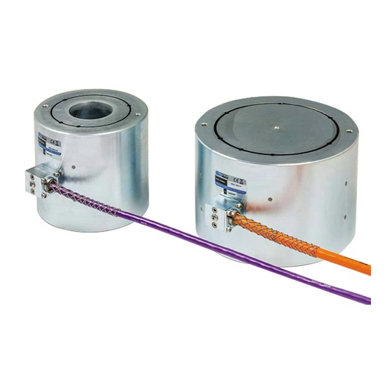
FIGURE 3: Load Cells for Load Monitoring During Pile Load Test 1.2 LOAD CELL DESIGN AND CONSTRUCTION The Model 4900 Load Cell body is constructed in the form of a high strength steel cylinder in which three to six vibrating wire strain gauges are embedded to measure the change of strain in the cylinder as it comes under load. -
Page 13: Friction Between The Bearing Plate And Load Cell
On some jobs where there MODEL 4900 VIBRATING WIRE LOAD CELL | INTRODUCTION | 3... -
Page 14: Warping Of The Bearing Plates And Bearing Plate Design
Eccentric loading can be minimized by using spherical bearing plates, but this is expensive and is rarely done. Spherical seats may be of some value during pile load testing where uniformity of the load on the top of the pile is highly desirable. 4 | INTRODUCTION | GEOKON... -
Page 15: Elastic Behavior
GEOKON observation of the best installation practices and adhesive post curing techniques. Model 4900 Load Cells are designed to keep the normal working GEOKON stresses below 30% of the yield stress of the load cell material. Wherever possible load cells are cycled to 150% of the design load prior to calibration. As long as the load cell is never overloaded above this range, the no-load reading will not change. -
Page 16: Installation
The cable can be protected by the use of flexible conduit, which can be supplied by GEOKON Terminal boxes with sealed cable entries are available from for all types GEOKON of applications. These allow many gauges to be terminated at one location with 6 | INSTALLATION | GEOKON... -
Page 17: Electrical Noise
(spark gaps) may be installed in the terminal box/multiplexer to provide a measure of transient protection. Terminal boxes and multiplexers available from provide locations for the GEOKON installation of these components. MODEL 4900 VIBRATING WIRE LOAD CELL | INSTALLATION | 7... - Page 18 Plasma surge arrestors can be epoxied into the instrument cable, close to the load cell. A ground strap then connects the surge arrestor to an earth ground, such as a grounding stake. Consult the factory for additional information on available lightning protection. 8 | INSTALLATION | GEOKON...
-
Page 19: Taking Readings
The GK-404 will continue to take measurements and display readings until the unit is turned off, either manually or by the Auto-Off timer (if enabled). For more information, consult the GK-404 manual. MODEL 4900 SERIES VIBRATING WIRE LOAD CELL | TAKING READINGS | 9... -
Page 20: Gk-405 Vibrating Wire Readout
If no reading displays or the reading is unstable, see Section 5 for troubleshooting suggestions. For more information, consult the GK-405 Instruction Manual. 10 | TAKING READINGS | GEOKON... -
Page 21: Readout In Load Units
21. To store data hit the 'Store' icon on the screen. The readings will be stored under that particular load cell file, the one created in Step 1. MODEL 4900 SERIES VIBRATING WIRE LOAD CELL | TAKING READINGS | 11... -
Page 22: Measuring Temperatures
48.5Ω per km (14.7Ω per 1000') at 20 °C. Multiply these factors by two to account for both directions. Look up the temperature for the measured resistance in Appendix B. 12 | TAKING READINGS | GEOKON... -
Page 23: Data Reduction
0.907 TABLE 1: Engineering Units Conversion Multipliers For example: Model 4900 VW Load Cells have a regression no-load reading (R ) of 7309 and a current average reading (R ) of 5497, and the calibration factor is –397 lbs. per digit. -
Page 24: Temperature Correction Factor
The actual temperature effect can only be arrived at empirically by simultaneous measurements of load and temperature over a short period of time. 14 | DATA REDUCTION | GEOKON... -
Page 25: Figure 9: Typical Model 4900 Calibration Sheet
FIGURE 9: Typical Model 4900 Calibration Sheet MODEL 4900 VIBRATING WIRE LOAD CELL | DATA REDUCTION | 15... -
Page 26: Troubleshooting
Is there a short? Check all connections, terminals, and plugs. If a short is located in the cable, splice according to instructions above. □ Water may have penetrated the interior of the load cell. There is no remedial action. 16 | TROUBLESHOOTING | GEOKON... -
Page 27: Appendix A. Specifications
Established under laboratory conditions. System accuracy depends on end loading conditions. Other cable types, e.g., armored, are available. A.2 THERMISTOR Range: -80 to +150 °C Accuracy: ±0.5 °C MODEL 4900 VIBRATING WIRE LOAD CELL | SPECIFICATIONS | 17... -
Page 28: Appendix B. Thermistor Temperature Derivation
166.7 58.3 21.89K 2872 582.6 162.0 56.8 20.70K 2750 562.8 157.6 55.6 19.58K 2633 543.7 153.2 18.52K 2523 525.4 149.0 17.53K 2417 507.8 145.0 16.60K 2317 490.9 141.1 TABLE 3: 3KΩ Thermistor Resistance 18 | THERMISTOR TEMPERATURE DERIVATION | GEOKON... -
Page 29: Appendix C. Wiring And Connector Pinouts
+12 VDC JP1-4 Green Violet Ground JP1-9 Green's Black Grey Mux Sense JP1-9 Blue White Mux Clock JP1-8 Blue's Black Black Mux Type JP1-9 TABLE 5: Module Wiring MODEL 4900 VIBRATING WIRE LOAD CELL | WIRING AND CONNECTOR PINOUTS | 19... -
Page 30: Appendix D. Load Cell Gauge Factor Recalculation
(The applied load was 291 tons). Repeat step four for subsequent readings or repeat all steps if more gauges in the load cell fail. 20 | LOAD CELL GAUGE FACTOR RECALCULATION | GEOKON... -
Page 31: Appendix E. Load Cell Calibrations - Effects Of Bearing Plate Warping
Simulated jack B had a bearing surface of 4" ID, 5¾" OD. Simulated jack C had a bearing surface of 6" ID, 8" OD. The maximum applied load was 150 tons. MODEL 4900 VIBRATING WIRE LOAD CELL | LOAD CELL CALIBRATIONS - EFFECTS OF BEARING PLATE WARPING | 21... -
Page 32: Conclusion
REFERENCES: J. Dunnicliff. 1988. Geotechnical Instrumentation for Monitoring Field Performance, John Wiley & Sons, New York, NY: 577pp. 22 | LOAD CELL CALIBRATIONS - EFFECTS OF BEARING PLATE WARPING | GEOKON... -
Page 33: Appendix F. Use Of The Regression Zero When Using The Linear Gauge Factor
MODEL 4900 VIBRATING WIRE LOAD CELL | USE OF THE REGRESSION ZERO WHEN USING THE LINEAR GAUGE FACTOR | 23... -
Page 34: Appendix G. Model 8032-27 And Load Cell Wiring
8032-27 may be wired into a GEOKON terminal or multiplexer board where the VW– signal would normally go. Wire in one black conductor from the 8032-27 for each gauge of the load cell. 24 | MODEL 8032-27 AND LOAD CELL WIRING | GEOKON... - Page 36 GEOKON Phone: +1 (603) 448-1562 GEOKON is an ISO 9001:2015 48 Spencer Street Email: info@geokon.com Lebanon, New Hampshire Website: www.geokon.com registered company 03766, USA...
Need help?
Do you have a question about the 4900 and is the answer not in the manual?
Questions and answers