Table of Contents
Advertisement
Quick Links
Installation Manual
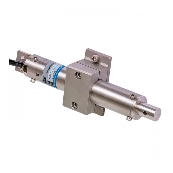
Model 6160/6161
MEMS Tilt Sensor
No part of this instruction manual may be reproduced, by any means, without the written consent of Geokon
®
.
The information contained herein is believed to be accurate and reliable. However, Geokon
®
assumes no responsibility for errors,
omissions or misinterpretation. The information herein is subject to change without notification.
Copyright © 2006-2019 by Geokon
®
(Doc Rev T, 05/01/2019)
Advertisement
Table of Contents

Subscribe to Our Youtube Channel
Related Manuals for Geokon 6160


Summary of Contents for Geokon 6160
- Page 1 Installation Manual Model 6160/6161 MEMS Tilt Sensor No part of this instruction manual may be reproduced, by any means, without the written consent of Geokon ® The information contained herein is believed to be accurate and reliable. However, Geokon ®...
- Page 3 Geokon or any breach of any warranty by Geokon shall not exceed the purchase price paid by the purchaser to Geokon for the unit or units, or equipment directly affected by such breach. Under no circumstances will Geokon reimburse the claimant for loss incurred in removing and/or reinstalling equipment.
-
Page 5: Table Of Contents
APPENDIX C. SAMPLE CALIBRATION REPORT ................... 14 APPENDIX D. WIRING CODES ..........................16 APPENDIX E. 6160 STANDARD ADDRESSABLE SYSTEMS ................17 APPENDIX F. PROGRAMMING THE MEMS TILTMETER WITH CRBASIC ..........19 APPENDIX G. PROGRAMMING THE ADDRESSABLE MEMS TILTMETER WITH CRBASIC ..... 20... - Page 6 FIGURES 1 - M 6160 MEMS T ......................1 IGURE ODEL ENSOR 2 - M 6160 T ................. 1 IGURE OUNTING RACKET FOR THE ODEL ENSOR 3 - M 6161A T ) ........2 IGURE ODEL ENSOR ERTICAL RIENTATION IAXIAL MODEL SHOWN...
-
Page 7: Introduction
There are two main types of Tilt Sensors: The Model 6160 is an adaption of the tiltmeter used in Model 6150 In-Place Inclinometer, and the 6161 utilizes the same MEMS sensors inside a Nema 4 enclosure. -
Page 8: Figure 3 - Model 6161A Tilt
Figure 3 - Model 6161A Tilt Sensor (Vertical Orientation, Biaxial model shown) Figure 4 - Model 6161B Tilt Sensor (Vertical Orientation, Biaxial model shown) -
Page 9: Installation
Checks of electrical continuity can also be made using an ohmmeter. Resistance between any conductor and the shield or the case should exceed two megohms. 2.2 Installing Model 6160 Sensors 2.2.1 Mounting Brackets The first step is to install the uniaxial/biaxial mounting bracket (Figure 5), which is designed for mounting on vertical walls. - Page 10 2.2.1.1 Mounting with a Drop-in Anchor 1) Mark the location where the bracket will be installed. 2) Using a hammer drill, drill a 12 mm (0.5") hole approximately 37 mm (1.5") deep. Clean the hole thoroughly, blowing out with compressed air if possible. 3) Insert the 3/8"...
-
Page 11: Figure 7 - Anchor Rod
2.2.1.2 Mounting with an Anchor Rod 1) Mark the location where the bracket will be installed. 2) Using a hammer drill, drill a 12 mm (0.5") hole approximately 100 mm (4") deep. 3) Clean the hole thoroughly, blowing out with compressed air if possible. 4) Mix the grout or epoxy and fill the hole. -
Page 12: Mounting The Sensor
2.2.2 Mounting the Sensor 1) Attach the tiltmeter to the mounting bracket using the supplied 10-32 cap screws, washers, and nuts. The cap screws should be installed finger-tight at this time. 2) Attach a portable readout such as the RB-500 to the tiltmeter and observe the reading. (See Section 3 for readout instructions.) 3) Adjust the sensor in the slot of the mounting bracket while observing the readout until the tiltmeter reads within ±0.15 volts of the zero reading shown on the calibration... -
Page 13: Sensor Protection
2.2.3 Sensor Protection If the tiltmeter is installed in an exposed location where damage due to vandalism, construction, or other factors might occur, it should be covered with a protective enclosure and/or insulation. For best results, the tiltmeter should be shielded from direct sunlight. 2.3 Installing Model 6161 Sensors 1) Place the tiltmeter on the mounting surface. -
Page 14: A Axis Tilt Adjustments
2.3.1 A Axis Tilt Adjustments 1) Use a Phillips head screwdriver to loosen the A axis adjustment screw (refer to Figure 9 below). 2) Adjust the position of the sensor mounting bracket until the A axis of the tiltmeter reads within ±0.15 volts of the zero reading shown on the calibration report supplied with the sensor. -
Page 15: Junction Boxes
(with integral shield drain wire). When splicing, it is very important that the shield drain wires be spliced together. Splice kits recommended by Geokon incorporate casts placed around the splice then filled with epoxy to waterproof the connections. When properly made, this type of splice is equal or superior to the cable in strength and electrical properties. -
Page 16: Taking Readings
3. TAKING READINGS 3.1 Dataloggers In most cases the 6160 and 6161 MEMS Tiltmeters will be monitored continuously and automatically using a Datalogger. Connector pin designations for the various tiltmeter models are shown in Appendix D. 3.2 RB-500 Readout Box The RB-500 readout box is designed to take readings for manually transcribing into a field book;... -
Page 17: Data Reduction
R is the current reading in volts is the reading at θ =zero zero G is the Gauge Factor shown on the calibration report for the Model 6160 tiltmeter. For measurements of tilt, i.e., changes of inclination, where R is the initial reading and R... -
Page 18: Troubleshooting
5. TROUBLESHOOTING Maintenance and troubleshooting of the MEMS sensors used in the Model 6160 and 6161 Tiltmeters are confined to periodic checks of cable connections. The sensors are sealed and there are no user serviceable parts. Consult the following list of problems and possible solutions should difficulties arise. Consult the factory for additional troubleshooting help. -
Page 19: Appendix A. Specifications
Polyurethane jacket, Foil shield, Polyurethane jacket, nominal OD = 7.9 mm Nominal OD = 6.3 mm Table 1 - Model 6160 and 6161 Tilt Sensor Specifications Notes: Depends on readout equipment. For best results requires a 4 ½ digit digital voltmeter. -
Page 20: Appendix B. Thermistor Temperature Derivation
APPENDIX B. THERMISTOR TEMPERATURE DERIVATION Thermistor Type: YSI 44005, Dale #1C3001-B3, Alpha #13A3001-B3 Resistance to Temperature Equation: A+B ( LnR ) +C(LnR) -273.15 °C Equation 4 - Resistance to Temperature Where; T = Temperature in °C. LnR = Natural Log of Thermistor Resistance. A = 1.4051 ×... -
Page 21: Appendix C. Sample Calibration Report
APPENDIX C. SAMPLE CALIBRATION REPORT Figure 10 - Sample Model 6160 Calibration Report... -
Page 22: Appendix D. Wiring Codes
APPENDIX D. WIRING CODES Biaxial MEMS Connector Pin Uniaxial MEMS with Connector Pin without 03-250V0 cable Designation Thermistor Designation Thermistor 12VDC 12VDC Red’s Black Ground Ground White A Out Diff + A Out Diff + White’s Black A Out Diff - A Out Diff - Bare Shield... -
Page 23: Appendix E. 6160 Standard Addressable Systems
APPENDIX E. 6160 STANDARD ADDRESSABLE SYSTEMS Description: The standard 6160 addressable system incorporates a Distributed Multiplexer Circuit Board that allows multiple MEMS type tiltmeters, uniaxial or biaxial, to be connected as “drops” off of a single bus. The tiltmeter “string” is addressed via ENABLE and CLOCK signals in the same manner as the Geokon Model 8032-16 Channel Multiplexer. -
Page 24: Table 5 - Thermistor Bridge
*1K and 5K precision resistors are used to complete the thermistor bridge circuit: Table 5 - Thermistor Bridge Circuit Specifications for Addressable System (Logic Level Style) Circuit Board: Board Dimensions: 4.5"(L) x 1.155"(W) x 0.4"(H) Power Requirements: +12V (± 3V) 110mA (max) when active 700uA (max) standby Operating Temperature:... -
Page 25: Appendix F. Programming The Mems Tiltmeter With Crbasic
APPENDIX F. PROGRAMMING THE MEMS TILTMETER WITH CRBASIC Description: CRBASIC is the programming Language used with Campbell Scientific CRBASIC Dataloggers. Campbell’s LoggerNet Software is typically used when programming in CRBASIC. The MEMS sensor should be read with the VoltDiff instruction and the output averaged 100x. (No Thermistor in this example.) Sample Program: 'Declare Public Variables for Reading MEMS Sensor... -
Page 26: Appendix G. Programming The Addressable Mems Tiltmeter With Crbasic
APPENDIX G. PROGRAMMING THE ADDRESSABLE MEMS TILTMETER WITH CRBASIC Description: CRBASIC is the programming Language used with Campbell Scientific CRBASIC Dataloggers. Campbell’s Loggernet Software is typically used when programming in CRBASIC. The MEMS sensor should be read with the VoltDiff instruction and the output averaged 100x. Sample Program: ‘The following sample program reads 20 addressable Bi-Axial MEMS Gauges and Thermistors. - Page 27 'counter for number of sensors For Channel = 1 To 20 '1st clock using C8 PortSet(8,1) Delay(0,10,MSEC) PortSet(8,0) Delay(0,10,MSEC) 'Delay Delay(0,100,mSec) 'Read the A-axis 'Reset the temporary storage location MEMS_3 = 0 'counter For MEMS_1 = 1 To 100 'differential voltage measurement on DIFF1 VoltDiff (MEMS_2,1,mV5000,1,False,0,1000,0.001,0) 'Sum the readings MEMS_3 = MEMS_3 + MEMS_2...
- Page 28 'Calculate the Average reading value Reading_B = MEMS_3 / 100 'Delay Delay(0,100,msec) 'Read the thermistor 'half bridge measurement - SE5 AND EX1 BrHalf(THERM_1,1,mV2500,5,VX1,1,2500,0,1000,250,2.5,0.0) 'Calculate the temperature THERM_2 = THERM_1 / 5000 THERM_3 = (2.5 - (THERM_2*1000) - THERM_1)/THERM_2 Reading_THERM = 1/(.0014051 + (.0002369*LOG(THERM_3)) + (.0000001019*(LOG(THERM_3)^3))) - 273.2 '2nd clock using C8 PortSet(8,1)
Need help?
Do you have a question about the 6160 and is the answer not in the manual?
Questions and answers