Sign In
Upload
Manuals
Brands
Geokon Manuals
Accessories
4900
Geokon 4900 Manuals
Manuals and User Guides for Geokon 4900. We have
1
Geokon 4900 manual available for free PDF download: Instruction Manual
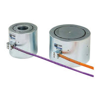
Geokon 4900 Instruction Manual (36 pages)
Vibrating Wire Load Cell
Brand:
Geokon
| Category:
Accessories
| Size: 1.39 MB
Table of Contents
Table of Contents
5
1 Introduction
11
Theory of Operation
11
Figure 1: Load Cells on Tiebacks for Monitoring
11
Load Cell Design and Construction
12
Figure 2: Load Cells on Tiebacks for Testing
12
Figure 3: Load Cells for Load Monitoring During Pile Load Test
12
Figure 4: Model 4900 Load Cell Side View
13
Figure 5: Typical Load Cell System
13
Friction between the Bearing Plate and Load Cell
13
Eccentric Loading
14
Warping of the Bearing Plates and Bearing Plate Design
14
Elastic Behavior
15
Temperature Effects
15
2 Installation
16
Preliminary Tests
16
Load Cell Installation
16
Transportation
16
Initial No-Load Reading
16
Installation on Tie-Backs and Rockbolts
16
Cable Installation and Splicing
16
Electrical Noise
17
Environmental Factors
17
Lightning Protection
17
3 Taking Readings
19
Gk-404 Vibrating Wire Readout
19
Operating the Gk-404
19
Figure 6: Gk-404 Readout
19
Figure 7: Lemo Connector to Gk-404
19
Gk-405 Vibrating Wire Readout
20
Connecting Sensors with 10-Pin Bulkhead Connectors
20
Attached
20
Connecting Sensors with Bare Leads
20
Operating the Gk-405
20
Figure 8: Gk-405 Readout
20
Readout in Load Units
21
Measuring Temperatures
22
4 Data Reduction
23
Load Calculation
23
Table 1: Engineering Units Conversion Multipliers
23
Equation 1: Digits Calculation
23
Equation 2: Load Calculation Using Linear Regression
23
Temperature Correction Factor
24
Equation 3: Load Calculation Using Polynomial
24
Equation 4: Load, Corrected for Temperature
24
Figure 9: Typical Model 4900 Calibration Sheet
25
5 Troubleshooting
26
Appendix A. Specifications
27
Model 4900 Load Cell Specifications
27
Thermistor
27
Table 2: Model 4900 Load Cell Specifications
27
Appendix B. Thermistor Temperature Derivation
28
Table 3: 3Kω Thermistor Resistance
28
Equation 5: 3Kω Thermistor Resistance
28
Appendix C. Wiring and Connector Pinouts
29
Load Cell Connector and Cable (Standard Wiring)
29
Gk-403 to Module Connector
29
Table 4: Standard Load Cell Wiring
29
Table 5: Module Wiring
29
Appendix D. Load Cell Gauge Factor Recalculation
30
Overview
30
Procedure
30
Table 6: Gauge Factor for Remaining Gauges
30
Appendix E. Load Cell Calibrations - Effects of Bearing Plate Warping
31
Introduction
31
Load Cell Calibration Procedures
31
Field Arrangement
31
Effects of Jack Size on Load Cell Reading
31
Conclusion
32
Table 7: Effects of Jack Sizing on Readings
32
Appendix F. Use of the Regression Zero When Using the Linear Gauge Factor
33
Appendix G. Model 8032-27 and Load Cell Wiring
34
Figure 10: Model 8032-27 Jumper Wire Assembly
34
Advertisement
Advertisement
Related Products
Geokon 4600
Geokon 4500HT-9-5
Geokon 4100 Series
Geokon 4150 Series
Geokon 4151
Geokon 4150-5
Geokon 4100-8
Geokon 4150-4
Geokon 4100-9
Geokon 4911
Geokon Categories
Measuring Instruments
Accessories
Data Loggers
Network Hardware
Industrial Equipment
More Geokon Manuals
Login
Sign In
OR
Sign in with Facebook
Sign in with Google
Upload manual
Upload from disk
Upload from URL