Sign In
Upload
Download
Table of Contents
Contents
Add to my manuals
Delete from my manuals
Share
URL of this page:
HTML Link:
Bookmark this page
Add
Manual will be automatically added to "My Manuals"
Print this page
×
Bookmark added
×
Added to my manuals
Manuals
Brands
Geokon Manuals
Accessories
4150 Series
Instruction manual
Geokon 4150 Series Instruction Manual
Vibrating wire strain gauges
Hide thumbs
1
2
3
4
Table Of Contents
5
6
7
8
9
10
11
12
13
14
15
16
17
18
19
20
21
22
23
24
25
26
27
28
29
30
31
32
33
34
35
36
37
38
39
40
41
42
43
44
45
46
47
48
page
of
48
Go
/
48
Contents
Table of Contents
Troubleshooting
Bookmarks
Table of Contents
Table of Contents
Introduction
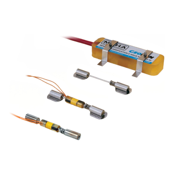
Figure 1: Model 4100 Vibrating Wire Strain Gauge
Figure 2: Model 4150 Vibrating Wire Strain Gauge
Figure 3: Model 4151 Vibrating Wire Strain Gauge
Preliminary Checks
Using a Readout
Using an Ohmmeter
Instrument Protection
Cable Splicing and Termination
Protection from Mechanical Damage
Securing Cables
Cover Plates
Figure 4: Model 4100 Cover Plate - Top View
Figure 5: Model 4150 Cover Plate - Top View
Figure 6: Cover Plate - End View
Cable and Connector Protection
Protection from Corrosion
Figure 7: Cover Plate Installation, Top View
Figure 8: Cover Plate Installation, Side View
Protection from Electrical Noise
Protection from Sunlight and Temperature Changes
Lightning Protection
Figure 9: Lightning Protection Scheme
Gauge Installation
Adjusting the Gauge Wire Tension
Installing the 4100/4150 Via Spot Welding
Prepare the Surface
Spot Weld Test Strips
Table 1: Guide to Initial Tension Settings
Spot Welding the 4100 Gauge
Spot Welding the 4150 Gauge
Figure 10: Peel Test
Figure 11: Spot-Welding Sequence, Outer Rows (4100)
Figure 12: Spot Welding Sequence, Outer Rows (4150)
Welding the Second End Piece
Installing Collar Shims
Figure 13: Spot Welding Sequence, Inner Rows
Figure 14: Using the Alignment Tool
Figure 15: Collar Shim
Figure 16: Welding the Collar Shim in Place
Figure 17: Completed Collar Shim
Installing the Plucking Coil Housing (Model 4100 Only)
Installing the Gauge Cover (Model 4150 Only)
Securing the 4150 Gauge Cable
Installing the 4100/4150 Via Epoxy Bonding
Figure 18: Spot Welded Cover Plate
Installing the 4151 Strain Gauge
Figure 19: Model 4151 Strain Gauge Installation
Gauge Location
End Effects
Welding Effects
Bending Moments
Figure 20: Strain Gauges Mounted on Central Web
Equation 1: Axial Stress Calculation
Equation 2: Stress Due to Bending on Axis Yy
Equation 3: Stress Due to Bending on Axis XX
Equation 4: Maximum Stress
Figure 21: Strain Gauges Mounted on Flanges
Figure 22: Axial Strain Measurement/Bending Moment about Yy Axis
Figure 23: Axial Strain and Bending Moment about XX Axis
Figure 24: Axial Strain and Bending Moment about Axis
Taking Readings
Strain Gauge Readout Positions
Gk-404 Vibrating Wire Readout
Operating the Gk-404
Figure 25: Gk-404 Readout
Figure 26: Lemo Connector to Gk-404
Table 2: Strain Gauge Readout Positions
Gk-405 Vibrating Wire Readout
Connecting Sensors with 10-Pin Bulkhead Connectors Attached
Connecting Sensors with Bare Leads
Operating the Gk-405
Figure 27: Gk-405 Readout
Measuring Temperatures
Data Reduction
Conversion of the Readings to Strain Changes
Converting Strains to Stresses
Equation 5: Theoretical Microstrain
Equation 6: Strain Calculation
Troubleshooting
Appendix A. Specifications
Vibrating Wire Strain Gauge
Thermistor
Figure 28: Gauge Assembly Dimensions
Figure 29: Cover Assembly Dimensions
Table 3: Specifications
Appendix B. Theory of Operation
Appendix C. Thermistor Temperature Derivation
3Kω Thermistor Resistance
Table 4: 3Kω Thermistor Resistance
Equation 7: 3Kω Thermistor Resistance
10Kω Thermistor Resistance
Table 5: 10Kω Thermistor Resistance
Equation 8: 10Kω Thermistor Resistance
Appendix D. Temperature Correction When Used on Concrete
Equation 9: Thermal Concrete Strains
Equation 10: Actual Strain
Equation 11: Strain Due to Load Changes Only
Appendix E. Temperature Effects
Equation 12: External Load Stress Only
Equation 13: Free Field Thermal Strains
Equation 14: Actual Strain
Appendix F. Calculations from Three Strain Gauges
Figure 30: Three Strain Gauges Mounted on a Circular Pipe
Equation 15: Average Axial Strain
Equation 16: Maximum Bending Strain Around the Yy Axis
Equation 17: Maximum Bending Strain Around the XX Axis
Equation 18: Maximum Strain
Appendix G. Model 4150-5 Extended Range Strain Gauge
Equation 19: Model 4150-5 Temperature Effects
Appendix H. Parts List
Table 6: Model 4100/4150 Series Model and Parts List
Advertisement
Quick Links
Download this manual
Model 4100/4150 Series
Vibrating Wire Strain Gauges
Instruction Manual
©2021, GEOKON. All rights reserved.
Document Revision: HH | Release date: 04/12/21
Table of
Contents
Previous
Page
Next
Page
1
2
3
4
5
Advertisement
Table of Contents
Need help?
Do you have a question about the 4150 Series and is the answer not in the manual?
Ask a question
Questions and answers
Related Manuals for Geokon 4150 Series
Accessories Geokon 4000 Series Instruction Manual
Vibrating wire strain gauges (46 pages)
Accessories Geokon 4600 Instruction Manual
Vw settlement sensor (28 pages)
Accessories Geokon 4600 Instruction Manual
Vw settlement sensor (19 pages)
Accessories Geokon 4900 Instruction Manual
Vibrating wire load cell (36 pages)
Accessories Geokon 4500HT-9-5 Connection Procedure
(12 pages)
Accessories Geokon 4100 Series Instruction Manual
Vibrating wire strain gauges (48 pages)
Accessories Geokon 6160 Installation Manual
Mems tilt sensor (28 pages)
Accessories Geokon RB-500 Instruction Manual
Mems sensor readout box (12 pages)
Accessories Geokon 6160 Installation Manual
Mems tilt sensor (28 pages)
Accessories Geokon 6160 Installation Manual
Mems tilt sensor (24 pages)
Table of Contents
Print
Rename the bookmark
Delete bookmark?
Delete from my manuals?
Login
Sign In
OR
Sign in with Facebook
Sign in with Google
Upload manual
Upload from disk
Upload from URL


Need help?
Do you have a question about the 4150 Series and is the answer not in the manual?
Questions and answers