Advertisement
Quick Links
Assembly Tips
Review entire instruction manual before proceeding.
•
Production Basics nameplate indicates front of frame.
•
Legs are adjustable in 2-inch increments between 30-36 or 30-42
•
inches high, depending on products ordered.
Don't be a slave to gravity-recruit a co-worker to help you install and
•
correctly position components and accessories.
References to 'Left' and 'Right' are oriented as if you were facing the
•
front of the workstation.
Need help? Call Assembly Support at 800.318.2770.
•
RTW Support Rail
(channel faces inward)
Production Basics, Inc.
Massachusetts, USA
ASSEMBLY VIDEOS AVAILABLE ON-LINE http://video.pbasics.com
A S S E M B L Y M A N U A L
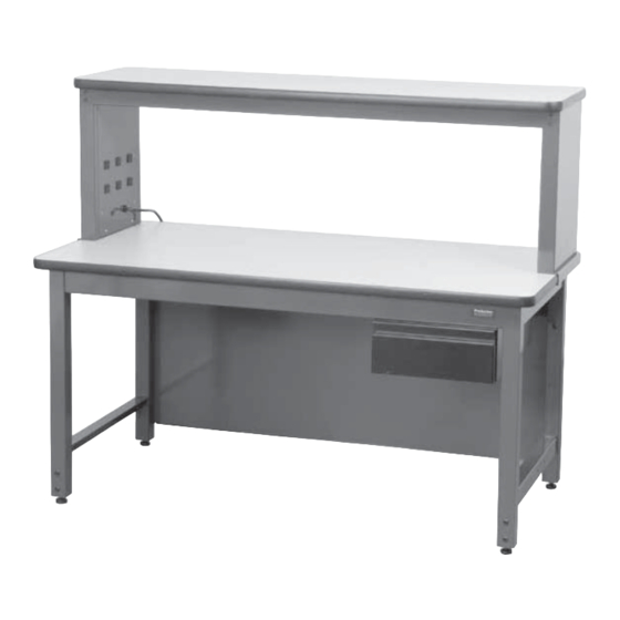
RTW Table with optional accessories
Right Frame Leg
(channel faces inward)
Mounting holes for Uprights
must be at back of Frame Leg.
800.318.2770
Workstations
RTW TABLE
Item Numbers 3000-3115
P A R T S A N D H A R D W A R E
Frame Legs (left and right speci c)
Leg Adjusters
RTW Support Rail
Chrome Mounting Plate
Worksurface
Leveling Feet
Wood Screws
Basic Bolts
7/32 Allen Wrench
Other Items Needed (not included)
Phillips head drill or screwdriver
Rubber mallet
Level
Tape Measure
Basic Bolt
Wood Screw
1. Open the cartons and identify the left and right Frame
Legs and RTW Support Rail. Position Frame Legs so
that mounting holes for Uprights are at the back of the
RTW Table. Frame Legs have a horizontal open channel
that faces inward.
2. Screw the levelling feet all the way into the leg adjusters.
2a. For casters assembly - Insert caster stem into leg
adjuster, lock caster and secure with nut and washer.
3. Slide leg adjusters into bottom of Frame Legs. Determine
desired table height and secure position by inserting two
(2) Basic Bolts. Adjust leveling feet if necessary.
617.926.8100
Fax: 617.926.8010
Q U A N T I T Y
2
4
2
4
1
4
12
16
1
Chrome Mounting Plate
www.pbasics.com
Advertisement

Related Manuals for Production Basics RTW


Summary of Contents for Production Basics RTW
- Page 1 Wood Screw 1. Open the cartons and identify the left and right Frame Legs and RTW Support Rail. Position Frame Legs so that mounting holes for Uprights are at the back of the RTW Table. Frame Legs have a horizontal open channel that faces inward.
- Page 2 The leg will be between the Chrome Mounting Plate and the Support Rail. Repeat for all sides and tighten bolts. 6. Invert the assembled RTW frame onto the underside of the worksurface. Position the worksurface and frame so Chrome Mounting Plate that it is ush with the back of unit with e ual overhang, left and right.
Need help?
Do you have a question about the RTW and is the answer not in the manual?
Questions and answers