Table of Contents
Advertisement
Quick Links
1004151333/308824414/26MM90476-PI23
USE AND CARE GUIDE
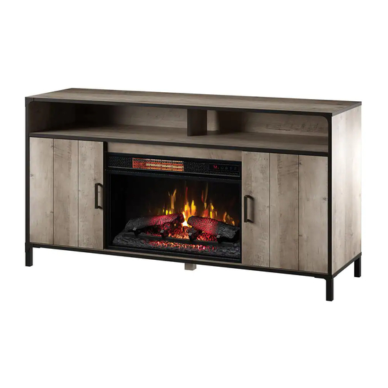
LYNHURST ELECTRIC FIREPLACE
QUESTIONS, PROBLEMS, MISSING PARTS? BEFORE RETURNING TO THE STORE,
CALL HOME DECORATORS COLLECTION CUSTOMER SERVICE
8 A.M. - 7 P.M., EST, MONDAY - FRIDAY, 9 A.M. - 6 P.M., EST, SATURDAY
1-800-986-3460
HOMEDEPOT.COM/HOMEDECORATORS
THANK YOU
We appreciate the trust and confidence you have placed in Home Decorators through the purchase of this electric fireplace. We strive to
continually create quality products designed to enhance your home. Visit us online to see our full line of products available for your home
improvement needs. Thank you for choosing Home Decorators!
Advertisement
Table of Contents

Related Manuals for Home Decorators Collection LYNHURST


Summary of Contents for Home Decorators Collection LYNHURST
- Page 1 USE AND CARE GUIDE LYNHURST ELECTRIC FIREPLACE QUESTIONS, PROBLEMS, MISSING PARTS? BEFORE RETURNING TO THE STORE, CALL HOME DECORATORS COLLECTION CUSTOMER SERVICE 8 A.M. - 7 P.M., EST, MONDAY - FRIDAY, 9 A.M. - 6 P.M., EST, SATURDAY 1-800-986-3460 HOMEDEPOT.COM/HOMEDECORATORS THANK YOU We appreciate the trust and confidence you have placed in Home Decorators through the purchase of this electric fireplace.
-
Page 2: Table Of Contents
Table of Contents Maximum Load Warning ........... 2 Package Contents .............. 7 Safety Information ............. 3 Assembly ..............8 Warranty ..............5 Operation ..............19 Pre-Assembly ............. 6 FCC/IC Information ............21 Hardware Included ........... 6 Care & Cleaning ............21 Product Specifications ............ -
Page 3: Safety Information
Safety Information Please read and understand this entire manual before WARNING: This appliance is hot when in use. To avoid attempting to assemble, operate or install the product. If you burns, do not touch hot surfaces with bare skin. If provided, have any question regarding the product, please call customer use handles when moving this appliance. - Page 4 Safety Information (continued) NOTE: Use care in assembling your new fireplace. Take your time and use the hardware provided and a quality Phillips head screwdriver. Never overtighten bolts. • Do not sit on any part of the mantel. NOTE: To avoid injury from unexpected starting or electrical shock, do not plug the power cord into a source of power during unpacking and assembly.
-
Page 5: Warranty
Warranty 1 Year Limited Warranty: The manufacturer warrants that your new Electric Fireplace is free from manufacturing and material defects for a period of one year from date of purchase, subject to the following conditions and limitations. Install and operate this appliance in accordance with the installation and operating instructions furnished with the product at all times. -
Page 6: Pre-Assembly
Pre-Assembly HARDWARE INCLUDED Part Description Part Number Quantity Shelf Pin PH-SPNPCSPLB2 Cam Lock Screw PH-KDBZNC001 Cam Lock Connector PH-KDCZNC001 Wood Dowel PH-DWLNTL001 Euro Hinge PH-HNG2H35CR95 Screw 3.5 x 15 mm PH-SCRNKL008 Screw 4 x 50 mm PH-SCRBLK006 Bolt 6.3 x 12 mm PH-BLTBLK002 Plastic Cover PH-KDPGRY001... -
Page 7: Package Contents
Pre-Assembly (continued) PACKAGE CONTENTS NOTE: All panels are labeled left and right as viewed from the front of unit. Part Description Quantity Bottom Shelf Left Surround Rail Right Surround Rail Left Partition Right Partition Top Surround Rail Top Panel Fixed Shelf Left Side Panel Right Side Panel Back Legs... -
Page 8: Assembly
Assembly Preparing the front surround Preparing the center panels Place the Left Surround Rail (B) and Right Surround Place the Left Partition (D) and Right Partition (E) on Rail (C) on a flat surface. a flat surface. Insert Cam Lock Screws (BB) into the pre-drilled holes Insert Wood Dowels (DD) into the pre-drilled holes in the Left Surround Rail (B). - Page 9 Assembly (continued) Preparing the center assembly Assembling center panels Locate the Top Surround Rail (F). Align the wood dowels on the Top Surround Rail (F) with Insert Wood Dowels (DD) into each end of the the pre-drilled holes on the Left Partition (D) and Right Top Surround Rail (F) as indicated.
- Page 10 Assembly (continued) Attaching the center shelf Attaching the surround bracket Align the cam lock screws and wood dowels on the Find the Metal Plate (LL) on the back of the Fixed Shelf (H) with the pre-drilled holes along the Top Surround Rail (F). edges of the center assembly.
- Page 11 Assembly (continued) Preparing the side panels Attaching the door hinges for assembly Locate the Left Side Panel (I) and Right Side Insert Cam Lock Screws (BB) into the pre-drilled holes Panel (J). in the Left Side Panel (I) and secure using a Phillips Locate the Euro Hinge (EE) and secure both the screwdriver.
- Page 12 Assembly (continued) Preparing for the bottom assembly Attaching the bottom shelf Insert Wood Dowels (DD) into the bottom edges of Locate the Bottom Shelf (A). the center assembly as indicated. Align the wood dowels on the bottom of the main assembly with the pre-drilled holes on the Bottom Shelf (A).
- Page 13 Assembly (continued) Preparing the center shelf Attaching the center foot for assembly Locate the Center Foot (L). Insert Wood Dowels (DD) into the center of the Fixed Attach the Center Foot (L) by twisting in a clockwise Shelf (H) on the main assembly as indicated in the motion, gently press against the bottom of the main diagram.
- Page 14 Assembly (continued) Preparing the top of the assembly Preparing the top panel Insert Wood Dowels (DD) into the pre-drilled holes in Place the Top Panel (G) onto a flat surface. the top edges of the main assembly. Insert the Cam Lock Screws (BB) into the pre-drilled holes in the bottom of the Top Panel (G).
- Page 15 Assembly (continued) Covering the screws Installing the back panels Push Plastic Covers (II) into the screw hole Locate the Upper Back Panel (N) and the Left and Right openings of areas that have already Side Panels (O, O). been assembled. Attach the Upper Back Panel (N) and Left and Right Side Panels (O, O) by inserting the Screws (JJ) through the pre-drilled holes in the back panels.
- Page 16 Assembly (continued) Preparing the doors Attaching the handles Locate the Euro Hinges (EE). Locate the Door Handle (PP) and use pre-attached Secure the Euro Hinges (EE) onto the Doors (P) using screws to secure on each door. the Screws (FF). Attach both the upper and lower hinges on each door as indicated by the diagram.
- Page 17 Assembly (continued) Attaching the adjustable shelves Installing the fireplace insert Insert the Shelf Pins (AA) into the pre-drilled holes Lift the Fireplace Insert (R) carefully into the back of the on the inside of both the left and right side cabinets. unit and center in the fireplace insert opening.
- Page 18 Assembly (continued) Adjusting the levelers The pre-attached Levelers (MM) are located under the base of the media unit. To level your assembled media unit, turn the Levelers as needed. HOMEDEPOT.COM/HOMEDECORATORS Please contact 1-800-986-3460 for further assistance.
- Page 19 Assembly (continued) Installing the tipping restraint hardware When the Tipping Restraint Hardware (SS) is properly installed, it can provide protection against unexpected Wall tipping of the Unit due to small tremors, bumps or climbing. Your Unit comes with two Tipping Restraint Hardware (SS).
-
Page 20: Operation
Operation Operation NOTE: The control panel can be accessed at the upper-right corner of the insert. Fig . 1 Powering the fireplace Adjusting the flame Push the Power button to supply power to all There are 6 brightness levels that can be selected: functions of the fireplace and put the insert in a standby mode. - Page 21 Operation (continued) Replacing the remote control battery Disposing of used batteries The battery may contain hazardous substances that When the remote control stops operating or its range could endanger the environment and human health. seems reduced, it is time to replace the batteries with new ones.
-
Page 22: Fcc/Ic Information
FCC/IC Information WARNING: Changes or modifications to this unit not expressly approved by the party responsible for compliance could void user’s authority to operate the equipment. NOTE: This equipment has been tested and found to comply with the limits for Class B digital device, pursuant to part 15 of the FCC Rules. -
Page 23: Troubleshooting
Troubleshooting PROBLEM ROOT CAUSE CORRECTIVE ACTION Unplug the fireplace, remove the back panel of the fireplace and check that the thermo- The thermostat sensor is stat is plugged into the main circuit board. Display shows " " broken or disconnected. If this does not solve the problem contact customer service for a replacement thermo- stat sensor. - Page 24 Troubleshooting (continued) PROBLEM ROOT CAUSE CORRECTIVE ACTION Flame effect works but heater func- With the power on press and hold the POWER tion does not and the emberbed flashes button on the control panel for 10 seconds. The heater is disabled. when the Heater button is pressed.
-
Page 25: Replacement Parts
Replacement Parts For replacement parts, call our customer service department at 1-800-986-3460, 8 a.m.-7 p.m., EST, Monday-Friday, 9 a.m. - 6 p.m., EST, Saturday. Part Description Qty. Remote Control Flame Circuit Board Blue LED Circuit Board Flame Generator Drive Motor Thermostat Sensor Blower/ Heater Assembly Control Panel Circuit Board... - Page 26 HOMEDEPOT.COM/HOMEDECORATORS Please contact 1-800-986-3460 for further assistance.
- Page 27 HOMEDEPOT.COM/HOMEDECORATORS Please contact 1-800-986-3460 for further assistance.
- Page 28 Questions, problems, missing parts? Before returning to the store call Home Decorators Customer Service 8 a.m. - 7 p.m., EST, Monday - Friday, 9 a.m. - 6 p.m., EST, Saturday 1-800-986-3460 HOMEDEPOT.COM/HOMEDECORATORS RETAIN THIS MANUAL FOR FUTURE USE.
Need help?
Do you have a question about the LYNHURST and is the answer not in the manual?
Questions and answers