Table of Contents
Advertisement
Available languages
Available languages
Safe Operation Practices • Set-Up • Operation • Service • Replacement Parts • Warranty
O
'
M
peratOr
s
anual
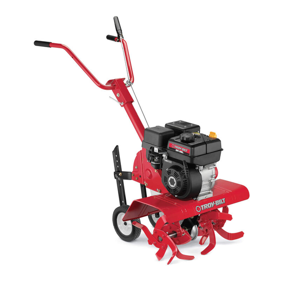
Front Tine Tiller — Colt FT
WARNING
READ AND FOLLOW ALL SAFETY RULES AND INSTRUCTIONS IN THIS MANUAL
BEFORE ATTEMPTING TO OPERATE THIS MACHINE.
FAILURE TO COMPLY WITH THESE INSTRUCTIONS MAY RESULT IN PERSONAL INJURY.
NOTE: This Operator's Manual covers several models. Features may vary by model. Not all features in this manual are applicable to all
models and the model depicted may differ from yours.
TROY-BILT LLC, P.O. BOX 361131 CLEVELAND, OHIO 44136-0019
Form No. 769-11849
(August 26, 2016)
Advertisement
Table of Contents

Related Manuals for Troy-Bilt Colt FT


Summary of Contents for Troy-Bilt Colt FT
- Page 1 NOTE: This Operator’s Manual covers several models. Features may vary by model. Not all features in this manual are applicable to all models and the model depicted may differ from yours. TROY-BILT LLC, P.O. BOX 361131 CLEVELAND, OHIO 44136-0019 Form No. 769-11849...
- Page 2 Choose from the options below: ◊ Visit us on the web at www.troybilt.com ◊ Call a Customer Support Representative at (800) 828-5500 or (330) 558-7220 ◊ Write to Troy-Bilt LLC • P.O. Box 361131 • Cleveland, OH • 44136-0019...
- Page 3 Important Safe Operation Practices WARNING! This symbol points out important safety instructions which, if not followed, could endanger the personal safety and/or property of yourself and others. Read and follow all instructions in this manual before attempting to operate this machine. Failure to comply with these instructions may result in personal injury.
- Page 4 the spark plug wire and ground it against the Notice Regarding Emissions If the machine should start making an engine to prevent unintended starting. unusual noise or vibration, stop the engine, disconnect the spark plug wire and ground Engines which are certified to comply with Do not change the engine governor settings it against the engine.
- Page 5 Assembly & Set-Up Contents of Carton • One Tiller • One Handlebar Assembly • One Depth Stake Assembly • Four Tine Assemblies • One Wheel Assembly • One Bottle of Oil • One Operator’s Manual • One Engine Operator’s Manual Assembly Use two clevis pins and two cotter pins from Remove the two screws from the bracket in...
- Page 6 Adjustments Remove the handle adjustment crank from the Adjust the forward clutch cable by loosening handle. See Figure 3-6. the hex nut. See Figure 3-9. Wheels The tiller is shipped with the wheels adjusted so that the machine sits level. The wheels need to be adjusted to meet your tilling needs before operation.
- Page 7 Controls & Operation Setting Depth - Wheels Back Place the wheels so that they are toward the rear Clutch Lever (closest to depth stake) for deep tilling and cultivating. See Figure 4-3. Handle HandleAdjustment Crank Depth Stake Figure 4-3 Setting Depth - Depth Stake Tines The depth stake acts as a brake for the tiller and controls the depth and speed at which the machine...
- Page 8 Using the Tiller Cultivating Procedures Your tiller is designed for seed bed preparation, For cultivating, a 2-3” depth is desirable. The tine cultivating, furrowing and mulching. width can be reduced to 13” by removing the outer tines completely from the tiller. See the Maintenance Tilling Procedure &...
- Page 9 Service Tines Removing/Installing a Single Tine WARNING! Disconnect the spark plug wire and ground it against the engine With the engine shut off and the spark plug Tilling Width before performing any repairs. wire disconnected, remove the two hex screws (3⁄8-16 x 1.00) and hex lock nuts (3⁄8-16) With the outer tines installed, the working width of Maintenance that attach a single tine to a tine holder.
- Page 10 Disconnect and ground the spark plug wire To install the new belt, follow the instructions against the engine. in reverse order and refer to Figure 5-4. Be sure Idler Pulley Keeper to place the wider side of the belt away from Remove the belt cover from the left side of the engine and transmission pulleys.
- Page 11 Replacement Parts Component Part Number and Description 642-04103 Inner LH Tine (A1) 642-04104 Inner RH Tine (B1) 642-04105 Outer LH Tine (A2) 642-04106 Outer RH Tine (B2) 714-04043 Cotter Pin 911-0415 Clevis Pin 954-0428 Drive Belt 746-04172 Clutch Cable 734-1268 Wheels, 8 x 1.75 Phone (800) 828-5500 to order replacement parts or a complete Parts Manual (have your full model number and serial number ready).
- Page 12 MANUFACTURER’S LIMITED WARRANTY FOR The limited warranty set forth below is given by Troy-Bilt LLC with Service completed by someone other than an authorized respect to merchandise purchased and used in the United States service dealer. and/or its territories and possessions (“Troy-Bilt”).
- Page 13 Medidas importantes de seguridad • Configuración • Funcionamiento • Servicio • Solución de problemas • Garantía anual del operador Cultivadora de dientes frontales — Colt FT ADVERTENCIA LEA Y SIGA TODAS LAS INSTRUCCIONES DE ESTE MANUAL ANTES DE PONER EN FUNCIONAMIENTO ESTA MÁQUINA.
- Page 14 Los números de teléfono, dirección del sitio web y dirección postal de la Asistencia al Cliente de Troy-Bilt se Por favor lea todo este manual antes de operar el equipo. Le indica encuentran en esta página.
- Page 15 Medidas importantes de seguridad ¡ADVERTENCIA! La presencia de este símbolo indica que se trata de instrucciones importantes de seguridad que se deben respetar para evitar poner en peligro su seguridad personal y/o material y la de otras personas. Lea y siga todas las instrucciones de este manual antes de poner en funcionamiento esta máquina.
- Page 16 Aviso referido a emisiones No sobrecargue la capacidad de la máquina Antes de limpiar, reparar o inspeccionar la intentando labrar el suelo a un nivel máquina, detenga el motor y asegúrese de demasiado profundo o a una velocidad que los dientes y todas las partes móviles Los motores que están certificados y cumplen demasiado rápida.
- Page 17 Montaje y Configuración Contenido de la caja de cartón • Una cultivadora • Un conjunto de barra de control • Un conjunto de calibrador de profundidad • Cuatro conjuntos de dientes • Una Asamblea de ruedas • Una botella de aceite •...
- Page 18 Ajustes Coloque el manija en su posición y asegure Girar la sección de collar cable de una o dos con el hardware eliminado previamente. Vea vueltas para aumentar o disminuir la tensión la Figura 3-5. Ruedas en el cable. Vea Figura 3-9. Retire la manivela de ajuste de la manija de la Vuelva a apretar la tuerca de seguridad contra El timón se entrega con las ruedas ajustadas para...
- Page 19 Controles y Funcionamiento Retén hacia atrás Coloque el retén de las ruedas de manera que las Palanca del ruedas están hacia atrás (punto más cercano a la embrague estaca de profundidad) para labranza profunda y cultivo. Vea la “Figura 4-2”. Manija Manija Ajuste Crank Estaca de...
- Page 20 Transporte y almacenamiento de la Procedimientos para realizar tareas de labranza cultivadora Es deseable una profundidad de dos a tres pulgadas para realizar la labranza del terreno. El ancho de Para transportar y almacenar la cultivadora mueva labranza se puede reducir a 13 pulgadas extrayendo el regulador a la posición ‘stop’...
- Page 21 Servicio Dientes Desmontaje / instalación de un único de dientes ¡ADVERTENCIA! Desconecte el cable de la bujía y tierra contra el motor antes Con el motor apagado y desconectado el Con los dientes exterior instalado, el ancho de de realizar cualquier reparación. trabajo de la máquina es de 24”.
- Page 22 Cuando almacene cualquier tipo de Retire la correa. NOTA: Retire el perno de la polea loca y mueva la equipo motorizado en un área sin ventilación correa desde debajo del guardacorreas de la Para instalar la nueva correa, siga las polea loca.
- Page 23 Notas...
- Page 24 Las disposiciones de esta garantía cubren el recurso de reparación incluidos en este manual anularán la garantía en lo que respecta a esos única y exclusiva que surge de la venta. Troy-Bilt no se hará responsable daños. de las pérdidas o los daños indirectos o emergentes, incluyendo sin Se garantiza que las piezas con desgaste normal están libres de...
Need help?
Do you have a question about the Colt FT and is the answer not in the manual?
Questions and answers
What is the spark plug gap setting on a TROY Colt FT
The spark plug gap setting for the Troy-Bilt Colt FT is not provided in the given context.
This answer is automatically generated