Table of Contents
Advertisement
Available languages
Available languages
Safe Operation Practices • Set-Up • Operation • Maintenance • Service • Troubleshooting • Warranty
O
'
M
peratOr
s
anual
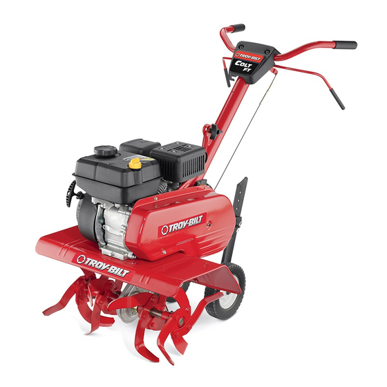
Front Tine Tiller — 340 Series
WARNING
READ AND FOLLOW ALL SAFETY RULES AND INSTRUCTIONS IN THIS MANUAL
BEFORE ATTEMPTING TO OPERATE THIS MACHINE.
FAILURE TO COMPLY WITH THESE INSTRUCTIONS MAY RESULT IN PERSONAL INJURY.
TROY-BILT LLC, P.O. BOX 361131 CLEVELAND, OHIO 44136-0019
Printed In USA
Form No. 769-08539
(October 15, 2012)
Advertisement
Chapters
Table of Contents

Subscribe to Our Youtube Channel
Related Manuals for Troy-Bilt Colt FT


Summary of Contents for Troy-Bilt Colt FT
- Page 1 READ AND FOLLOW ALL SAFETY RULES AND INSTRUCTIONS IN THIS MANUAL BEFORE ATTEMPTING TO OPERATE THIS MACHINE. FAILURE TO COMPLY WITH THESE INSTRUCTIONS MAY RESULT IN PERSONAL INJURY. TROY-BILT LLC, P.O. BOX 361131 CLEVELAND, OHIO 44136-0019 Printed In USA Form No. 769-08539...
-
Page 2: Table Of Contents
Visit us on the web at www.troybilt.com See How-to Maintenance and Parts Installation Videos at www.troybilt.com/tutorials ◊ Call a Customer Support Representative at (800) 828-5500 or (330) 558-7220 ◊ Write to Troy-Bilt LLC • P.O. Box 361131 • Cleveland, OH • 44136-0019... -
Page 3: Safe Operation Practices
Important Safe Operation Practices WARNING! This symbol points out important safety instructions which, if not followed, could endanger the personal safety and/or property of yourself and others. Read and follow all instructions in this manual before attempting to operate this machine. Failure to comply with these instructions may result in personal injury. - Page 4 When practical, remove gas-powered equipment After striking a foreign object, stop the engine, disconnect from the truck or trailer and refuel it on the ground. the spark plug wire and ground against the engine. If this is not possible, then refuel such equipment on Thoroughly inspect the machine for any damage.
- Page 5 Spark Arrestor If the fuel tank has to be drained, do this outdoors. Observe proper disposal laws and regulations for gas, oil, WARNING! This machine is equipped with an etc. to protect the environment. internal combustion engine and should not be used According to the Consumer Products Safety Commission on or near any unimproved forest-covered, (CPSC) and the U.S.
- Page 6 Safety Symbols This page depicts and describes safety symbols that may appear on this product. Read, understand, and follow all instructions on the machine before attempting to assemble and operate. Symbol Description READ THE OPERATOR’S MANUAL(S) Read, understand, and follow all instructions in the manual(s) before attempting to assemble and operate WARNING—...
-
Page 7: Assembly & Set-Up
Assembly & Set-Up Contents of Carton • One Tiller • One Handlebar Assembly • One Depth Gage Assembly • One Operator’s Manual • One Engine Operator’s Manual Assembly Hook the “Z” end of the forward clutch cable into the tine engagement lever Figure 1-2. - Page 8 Tighten the bolt securely after securing the handle brace as Insert the depth stake assembly into the frame and reinstall seen in Figure 1-4. the two screws removed earlier. Tighten the hex bolts securely. See Figure 1-6. Depth Stake Assembly Hand Knob Carriage Screw Screws...
- Page 9 Clutch Cable Adjustment Before operating the tiller the adjustment of the forward clutch cables must be checked. Disconnect and ground the spark plug wire against the engine. Adjust the forward clutch cable by loosening the hex nut. See Figure 1-8. Cable Collar Hex Nut Figure 1-8...
-
Page 10: Controls
Controls & Features Handle Forward Tine Engagement Lever Handle Knob Depth Stake Tiller Tines Tiller Tines Engine Controls Tilling tines are used to cultivate, furrow and prepare your See the separate Engine Operator’s Manual for information and garden for seeding. functions of the engine controls. -
Page 11: Operation
Operation Starting & Stopping the Engine Yoke to Back Place the wheel yoke so that wheels are toward the rear — closest WARNING! Read, understand, and follow all the to depth stake — for deep tilling and cultivating. See Figure 1-2. instructions and warnings posted on the machine and in this manual before operating. - Page 12 Handle Pressure Cultivating Procedures Further control of the tilling depth and travel speed can be For cultivating, a 2-3” depth is desirable. The tine width can obtained by variation of pressure on the handles. be reduced to 13” by removing the outer tines completely from the tiller.
-
Page 13: Maintenance & Adjustment
Maintenance & Adjustments Tines WARNING! Disconnect the spark plug wire and ground it against the engine before performing any Tilling Width repairs. With the outer tines installed, the working width of the machine Maintenance is 24”. This width may be expanded to 26” by removing the clevis and cotter pins, sliding each outer tine outward away from the Engine center of the tiller and re-securing the pins in the holes provided. -
Page 14: Tine Inspection
Off-Season Storage Tine Inspection The bolo tines will wear with use and should be inspected If the tiller will not be used for a period longer than 30 days, the at the beginning of each tilling season and after every 30 following steps should be taken to prepare the tiller for storage. -
Page 15: Service
Service Belt Replacement Using a 1⁄2” wrench, remove the hex screw securing the belt keeper to the engine. See Figure 1-3. Your tiller has been engineered with a belt made of special material (Kevlar Tensile) for longer life and better performance. It should not be replaced with an off-the-shelf belt. -
Page 16: Troubleshooting
Troubleshooting Problem Cause Remedy Tines do not engage 1. Foreign object lodged in tines 1. Dislodge foreign object 2. Tine clevis pin(s) missing 2. Replace tine clevis pin(s) 3. Pulley and idler not in correct adjustment 3. Take tiller to authorized service dealer 4. -
Page 17: Replacement Parts
Replacement Parts Component Part Number and Description 642-04103 Inner Left Hand Tine 642-04104 Inner Right Hand Tine 642-04105 Outer Left Hand Tine 642-04106 Outer Right Hand Tine 714-04043 Cotter Pin 911-0415 Clevis Pin 954-0428 Drive Belt 946-0918 Forward Cable 734-04538 Wheels, 8 x 1.75 Phone (800) 828-5500 to order replacement parts or a complete Parts Manual (have your full model number and serial number ready). -
Page 18: Warranty
MANUFACTURER’S LIMITED WARRANTY FOR The limited warranty set forth below is given by Troy-Bilt LLC with Log splitter pumps, valves, and cylinders have a separate one- year warranty. respect to new merchandise purchased and used in the United States and/or its territories and possessions, and by MTD Products... - Page 19 LEA Y SIGA TODAS LAS INSTRUCCIONES DE ESTE MANUAL ANTES DE PONER EN FUNCIONAMIENTO ESTA MÁQUINA. SI NO RESPETA ESTAS INSTRUCCIONES PUEDE PROVOCAR LESIONES PERSONALES. TROY-BILT LLC, P.O. BOX 361131 CLEVELAND, OHIO 44136-0019 Impreso en Estados Unidos de América Formulario No. 769-08539...
- Page 20 Ver Vídeos demostrativos de instalación de mantenimiento y piezas en www.troybilt.com/Tutorials ◊ Llame a un representante de Asistencia al Cliente al (800) 828-5500 ó (330) 558-7220 ◊ Escríbanos a Troy-Bilt LLC • P.O. Box 361131 • Cleveland, OH • 44136-0019...
-
Page 21: Importante Medidas Importantes De Seguridad
Medidas importantes de seguridad ¡ADVERTENCIA! La presencia de este símbolo indica que se trata de instrucciones importantes de seguridad que se deben respetar para evitar poner en peligro su seguridad personal y/o material y la de otras personas. Lea y siga todas las instrucciones de este manual antes de poner en funcionamiento esta máquina. - Page 22 Manejo seguro de la gasolina: Tenga cuidado cuando labre tierras duras. Los dientes pueden clavarse en la tierra e impulsar la cultivadora Para evitar lesiones personales o daños materiales tenga mucho hacia adelante. Si esto ocurre, suelte el manubrio y deje la cuidado cuando trabaje con gasolina.
- Page 23 Aviso referido a emisiones Antes de limpiar, reparar o inspeccionar la máquina, detenga el motor y asegúrese de que los dientes y todas las partes móviles se hayan detenido. Desconecte el cable Los motores que están certificados y cumplen con las de la bujía y póngalo haciendo masa contra el motor para regulaciones de emisiones federales EPA y de California para evitar que se encienda accidentalmente.
- Page 24 Símbolos de Seguridad Esta página describe los símbolos y figuras de seguridad internacionales que pueden aparecer en este producto. Lea el manual del operador para obtener la información terminada sobre seguridad, reunirse, operación y mantenimiento y reparación. Símbolo Descripción LEA EL MANUAL DEL OPERADOR (S) Lea, entienda, y siga todas las instrucciones en el manual (es) antes de intentar reunirse y funcionar.
-
Page 25: Ensamblado Y Configuración
Montaje y Configuración Contenido de la caja de cartón • Una cultivadora • Un conjunto de barra de control • Un conjunto de calibrador de profundidad • Un Manual de operación • Un Manual de operación del motor Montaje Enganche el extremo “Z” del cable del embrague de marcha adelante en la palanca de enganche de los dientes. - Page 26 Inserte el perno a través de la arandela cónica, el bastidor, Introduzca el conjunto de la estaca de profundidad en el la manija y dentro de la ménsula de guía del cable (observe cuadro y volver a instalar los dos tornillos que quitó antes. que la muesca de la ménsula de la guía del cable pasa por Apriete los tornillos hexagonales de forma segura.
- Page 27 Ajustes Ajuste del cable De vez en cuando puede ser necesario ajustar la tensión en el cable de la participación de dientes hacia adelante. Desconecte y el suelo cable de la bujía contra el motor. Ajuste el cable del embrague hacia delante, aflojando la tuerca hexagonal.
-
Page 28: Controles Y Características
Controles y Características Mango Marcha directa de dientes Palanca de enganche Perilla de la manija Estaca de profundidad Dientes de la cultivadora Dientes de la cultivadora Controles del motor Los dientes se utilizan para cultivar, surcar y preparar su jardín Consulte el Manual de operación del motor, por separado, para para la siembra. -
Page 29: Funcionamiento
Funcionamiento Arranque y detención del motor Retén hacia atrás Coloque el retén de las ruedas de manera que las ruedas están ¡ADVERTENCIA! Lea, comprenda y siga todas las hacia atrás (punto más cercano a la estaca de profundidad) para instrucciones y advertencias que se encuentran en la labranza profunda y cultivo. - Page 30 Presión de las manijas Procedimientos para realizar tareas de labranza Se puede obtener un mayor control de la profundidad de la Es deseable una profundidad de dos a tres pulgadas para realizar labranza y de la velocidad de recorrido variando la presión sobre la labranza del terreno.
-
Page 31: Mantenimiento Y Ajustes
Mantenimiento y Ajustes Dientes ¡ADVERTENCIA! Desconecte el cable de la bujía y tierra contra el motor antes de realizar cualquier Con los dientes exterior instalado, el ancho de trabajo de la reparación. máquina es de 24 pulgadas. Esta anchura se puede ampliar a 26 pulgadas por la eliminación de la horquilla y pasadores, Mantenimiento correderas cada diente hacia el exterior exterior del centro de la... - Page 32 Dientes Inspección Instale cada conjunto de dientes para que la corte (en punto) el borde de los dientes que penetran en el suelo Los dientes bolo se desgasta con el uso y deben ser por primera vez cuando el timón se mueve hacia adelante. inspeccionadas al inicio de cada temporada de cultivo y después Asegure el conjunto de dientes en el eje de púas con el cada 30 horas de funcionamiento.
-
Page 33: Servicio
Servicio Cambio de correa El uso de un 1⁄2“ llave, retire el tornillo hexagonal de fijación del cinturón de guardián en el motor. Vea la Figura 1-3. El diseño de la cultivadora incluye una correa de material especial (Kevlar Tracción) que le proporciona mayor duración y mejor rendimiento. -
Page 34: Solución De Problemas
Solución de problemas Problema Causa Remedio Los dientes no enganchan 1. Hay un objeto extraño entre los dientes 1. Desaloje el objeto extraño. 2. Falta la o las chavetas de horquilla de los 2. Cambie la o las chavetas de horquilla de los dientes. - Page 35 Notas...
- Page 36 Las disposiciones de esta garantía cubren el recurso de reparación comenzando la fecha de la compra o del arriendo original. única y exclusiva que surge de la venta. Troy-Bilt no se hará Accesorios — Troy-Bilt garantiza que los accesorios de este producto responsable de ninguna pérdida o daño incidental o resultante,...
Need help?
Do you have a question about the Colt FT and is the answer not in the manual?
Questions and answers
RECOMMENDED OIL CAPACITY FOR THE TROY BUILT COLT FT 208 CC