Table of Contents
Advertisement
Quick Links
Advertisement
Table of Contents

Related Manuals for Peak PCAN-USB X6


Summary of Contents for Peak PCAN-USB X6
- Page 1 PCAN-USB X6 User Manual User Manual 2.0.0 © 2022 PEAK-System Technik GmbH...
-
Page 2: Imprint
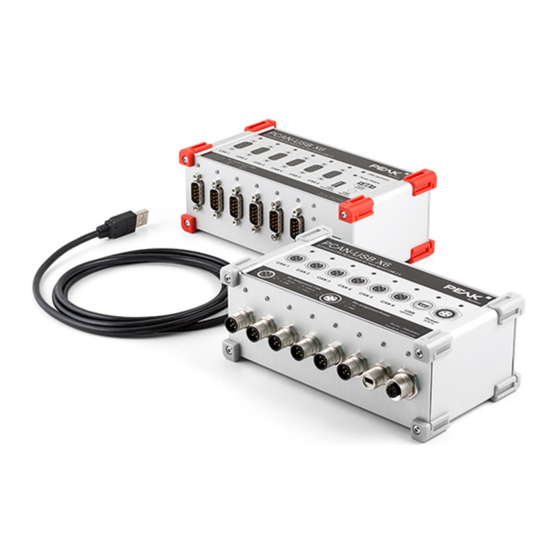
The cover picture shows the products PCAN-USB X6 with M12 connectors (left) and with D-Sub connectors (right). Imprint PCAN is a registered trademark of PEAK-System Technik GmbH. CiA® is a registered community trade mark of CAN in Automation e.V. All other product names in this document may be the trademarks or registered trademarks of their respective companies. -
Page 3: Table Of Contents
3.4 Connect the CAN-Bus 3.5 Example Application under Windows 4 Operation 4.1 Status LEDs 4.2 Unplugging the USB Connection 4.3 Distinguishing Several PCAN-USB X6 5 CAN Monitor PCAN-View 5.1 CAN interface initialize 5.2 Transmit CAN message 5.3 Additional Tabs 6 API PCAN-Basic 6.1 Features of PCAN-Basic... - Page 4 PCAN-USB X6 with M12 Connectors Appendix C Quick Reference Appendix D Linux Contents PCAN-USB X6 User Manual 2.0.0 © 2022 PEAK-System Technik GmbH...
-
Page 5: Introduction
Device drivers and application information for Linux: www.peak-system.com/quick/DL-Driver-E At the end of this manual you can find a Quick Reference with brief information about the installation and operation of the CAN interface. 1 Introduction PCAN-USB X6 User Manual 2.0.0 © 2022 PEAK-System Technik GmbH... -
Page 6: Properties At A Glance
Induced error generation for incoming and outgoing CAN messages ■ Power supply from 8 to 30 V ■ Extended operating temperature range from -40 to 85 °C (-40 to 185 °F) ■ 1 Introduction PCAN-USB X6 User Manual 2.0.0 © 2022 PEAK-System Technik GmbH... -
Page 7: System Requirements
Device drivers for Windows 11, 10 (32/64-bit) and Linux (32/64-bit) ■ CAN monitor PCAN-View for Windows ■ Programming interface PCAN-Basic for developing applications with CAN ■ connection Programming interfaces for standardized protocols from the automotive sector ■ 1 Introduction PCAN-USB X6 User Manual 2.0.0 © 2022 PEAK-System Technik GmbH... -
Page 8: Connectors
The power supply is possible in a range from 8 to 30 V DC. The "Power" input is electronically protected with reverse polarity and overvoltage protection. The power supply is connected via the supplied mating connector. Power supply Mating connector Polarity 2 Connectors PCAN-USB X6 User Manual 2.0.0 © 2022 PEAK-System Technik GmbH... - Page 9 For general use of USB devices. The USB Downstream port is passed through to the computer and is used to connect another USB device to the computer. Malfunction! Connecting another CAN interface to the USB downstream port is not as intended. 2 Connectors PCAN-USB X6 User Manual 2.0.0 © 2022 PEAK-System Technik GmbH...
-
Page 10: Pcan-Usb X6 With M12 Connectors
The power supply is connected via the supplied power cable: The pin assignment is as follows: M12 female panel connector M12 male cable connector on Assignment „Power“ power cable none none 2 Connectors PCAN-USB X6 User Manual 2.0.0 © 2022 PEAK-System Technik GmbH... - Page 11 The distance between the M12 male panel connector is 19 mm. Therefore, the maximum outer diameter of the M12 female cable connector is limited to 18 mm for a proper connection. 2 Connectors PCAN-USB X6 User Manual 2.0.0 © 2022 PEAK-System Technik GmbH...
-
Page 12: Internal Termination
PCAN-Term (IPEK-003002) or PCAN-MiniTerm (IPEK-003002-Mini). Thus, CAN nodes can be flexibly connected to the bus. Further notes on termination with terminating resistors can be found in chapter 2.4 Cabling. 2 Connectors PCAN-USB X6 User Manual 2.0.0 © 2022 PEAK-System Technik GmbH... - Page 13 6. Insert the board including the mainboard carefully back into the case. PCAN-USB X6 with M12 connectors: Make sure that the seal is correctly seated. 7. Fasten the front panel with the four Torx screws. 2 Connectors PCAN-USB X6 User Manual 2.0.0 © 2022 PEAK-System Technik GmbH...
- Page 14 Top view on the solder fields (red) and transceiver modules (dark grey) of the mainboard Solder fields: CAN1: JP1, JP2 CAN2: JP3, JP4 CAN3: JP5, JP6 CAN4: JP7, JP8 CAN5: JP9, JP10 CAN6: JP11, JP12 2 Connectors PCAN-USB X6 User Manual 2.0.0 © 2022 PEAK-System Technik GmbH...
-
Page 15: Cabling
2.4.2 Example of a Connection This example shows a connection between the PCAN Interface and a control unit (ECU). The upper example shows a connection with a cable which is terminated with 2 Connectors PCAN-USB X6 User Manual 2.0.0 © 2022 PEAK-System Technik GmbH... - Page 16 125 kbit/s 500 m 50 kbit/s 1.3 km 25 kbit/s 2.5 km The listed values have been calculated on the basis of an idealized system and can differ from reality. 2 Connectors PCAN-USB X6 User Manual 2.0.0 © 2022 PEAK-System Technik GmbH...
-
Page 17: Installation
Install the driver before you connect the CAN interface. 3.1 Install Device Driver Setup 1. Download the device driver setup from our website: www.peak-system.com/quick/DL-Driver-E 2. Unpack the file PEAK-System_Driver-Setup.zip 3. Double-click the file PeakOemDrv.exe The driver setup starts. 4. Follow the program instructions. -
Page 18: Connect The Can-Bus
Connect a CAN bus to each of one or more CAN ports. 3.5 Example Application under Windows As an example application for accessing the CAN interface, run the CAN monitor PCAN-View from the Windows Start menu. 3 Installation PCAN-USB X6 User Manual 2.0.0 © 2022 PEAK-System Technik GmbH... -
Page 19: Operation
There is only a connection via the USB upstream. The device is not ready Orange on for use. power Supply The status LED of the power supply can assume the following states: Status Meaning Green on A power supply is connected. 4 Operation PCAN-USB X6 User Manual 2.0.0 © 2022 PEAK-System Technik GmbH... -
Page 20: Unplugging The Usb Connection
PCAN-USB X6. You can unplug the PCAN-USB X6 from the computer without any preparation. 4.3 Distinguishing Several PCAN-USB X6 You can operate several PCAN-USB X6 on a single computer at the same time. The supplied program PCAN-View allows the assignment of device IDs in order to distinguish the several CAN interfaces in a software environment. -
Page 21: Can Monitor Pcan-View
In the following the initialization of a CAN interface is described as an example. Detailed information about using PCAN-View can be found in the program window under the menu item Help. 5 CAN Monitor PCAN-View PCAN-USB X6 User Manual 2.0.0 © 2022 PEAK-System Technik GmbH... -
Page 22: Can Interface Initialize
2. If there are several CAN interfaces, select the desired interface. For multiple channels, select the desired channel from the list. 3. Enter the bit rate(s) and other settings according to the connected CAN bus. 5 CAN Monitor PCAN-View PCAN-USB X6 User Manual 2.0.0 © 2022 PEAK-System Technik GmbH... - Page 23 4. Confirm the entries with OK. The main window appears and displays the Receive / Transmit tab. 5. For initializing another channel or CAN interface, open another instance of PCAN- View. 5 CAN Monitor PCAN-View PCAN-USB X6 User Manual 2.0.0 © 2022 PEAK-System Technik GmbH...
-
Page 24: Transmit Can Message
4. To send the message manually, select the menu command Transmit > Send or press the |space| bar. The manual transmission process is performed additionally for periodically transmitted CAN messages. 5 CAN Monitor PCAN-View PCAN-USB X6 User Manual 2.0.0 © 2022 PEAK-System Technik GmbH... -
Page 25: Additional Tabs
5.3.1 Trace Tab The tracer (data logger) records the communication of the CAN bus in linear or ring buffer mode. The trace data can be saved to a file. 5 CAN Monitor PCAN-View PCAN-USB X6 User Manual 2.0.0 © 2022 PEAK-System Technik GmbH... - Page 26 CAN interface, a hardware ID can be determined to distinguish several interfaces of the same type. For interfaces with CAN FD a transmission according to "ISO" or "Non-ISO" can be set as default of the hardware. 5 CAN Monitor PCAN-View PCAN-USB X6 User Manual 2.0.0 © 2022 PEAK-System Technik GmbH...
- Page 27 5.3.3 Bus Load Tab The Bus Load tab displays the current bus load, its time history and statistical information of the connected CAN channel. 5.3.4 Error Generator Tab 5 CAN Monitor PCAN-View PCAN-USB X6 User Manual 2.0.0 © 2022 PEAK-System Technik GmbH...
- Page 28 You can destroy CAN frames with the error generator by one of two methods: once after activation ■ repeatedly at specific intervals related to a CAN ID ■ 5 CAN Monitor PCAN-View PCAN-USB X6 User Manual 2.0.0 © 2022 PEAK-System Technik GmbH...
- Page 29 4. Determine the Number of Frames to destroy. 5. Confirm the entries with Apply to activate the error generator. 6. Stop destroying further CAN frames with Disable. 5 CAN Monitor PCAN-View PCAN-USB X6 User Manual 2.0.0 © 2022 PEAK-System Technik GmbH...
-
Page 30: Api Pcan-Basic
The programming interface (API) PCAN-Basic provides basic functions for the connection of own programs to the CAN interface of PEAK-System. PCAN-Basic is the interface between the program and the device driver. In Windows operating systems this is a DLL (Dynamic Link Library) and in Linux operating systems an SO (Dynamic Shared Object). -
Page 31: Features Of Pcan-Basic
■ Windows 11, 10 (32/64-bit) ■ Linux (32/64-bit) ■ Multiple PEAK-System applications and your own can be operated on a physical ■ channel at the same time Single DLL (Win) / SO (Linux) for all supported hardware types ■ Use of up to 16 channels for each hardware type ■... -
Page 32: Principle Description Of The Api
To end the communication the function CAN_Uninitialize is called in order to release the reserved resources for the CAN channel, among others. In addition the CAN channel is marked as "Free" and is available to other applications. 6 API PCAN-Basic PCAN-USB X6 User Manual 2.0.0 © 2022 PEAK-System Technik GmbH... -
Page 33: Technical Data
FPGA implementation Time stamp resolution 1 µs Galvanic isolation up to 300 V, separate for each CAN connector (nur IPEH-004063/-64) Internal Termination via solder bridges, disabled at delivery 7 Technical Data PCAN-USB X6 User Manual 2.0.0 © 2022 PEAK-System Technik GmbH... - Page 34 Ingress protection (IEC 60529) IP64 for IPEH-004063 Conformity Directive 2011/65/EU (RoHS 2) + 2015/863/EU RoHS DIN EN IEC 63000:2019-05;VDE 0042-12:2019-05 Directive 2014/30/EU EN 55024:2016-05;VDE 0878-24:2016-05 EN 55032:2016-02;VDE 0878-32:2016-02 7 Technical Data PCAN-USB X6 User Manual 2.0.0 © 2022 PEAK-System Technik GmbH...
-
Page 35: Appendix A Ce Certificate
Appendix A CE Certificate Appendix A CE Certificate PCAN-USB X6 User Manual 2.0.0 © 2022 PEAK-System Technik GmbH... -
Page 36: Appendix B Dimension Drawings
Appendix B Dimension Drawings PCAN-USB X6 with D-Sub Connectors Dimensions in mm. Appendix B Dimension Drawings PCAN-USB X6 User Manual 2.0.0 © 2022 PEAK-System Technik GmbH... - Page 37 PCAN-USB X6 with M12 Connectors Dimensions in mm. Appendix B Dimension Drawings PCAN-USB X6 User Manual 2.0.0 © 2022 PEAK-System Technik GmbH...
- Page 38 There is no supply via the USB connection to the PC. Software/Hardware Installation under Windows Download the device drivers installation package from our website www.peak-system.com/quick/DL-Driver-E. Install the driver before you install the CAN interface. Malfunction! Do not use a USB extension cable to connect the PCAN-USB X6 to the computer.
- Page 39 There is only a connection via the USB upstream. The device is not ready Orange on for use. Note: The status LED of the USB upstream is only lit, when it is connected to a USB 2.0 port or higher. Appendix C Quick Reference PCAN-USB X6 User Manual 2.0.0 © 2022 PEAK-System Technik GmbH...
- Page 40 Appendix D Linux Depending on the Kernel version, device drivers for the CAN interfaces from PEAK- System are already included in the operating system. The CAN interfaces are treated as network devices (SocketCAN, netdev). You can find the documentation for SocketCAN under: https://www.kernel.org/doc/Documentation/networking/can.txt...
Need help?
Do you have a question about the PCAN-USB X6 and is the answer not in the manual?
Questions and answers