
Related Manuals for BEKA BA488C


Summary of Contents for BEKA BA488C
- Page 1 BA488C Intrinsically safe Panel mounting Modbus RTU display Serial Data display Issue 15 Issue: 15 October 2020...
-
Page 2: Table Of Contents
5.2.5 Four wire system 5.3 Switch outputs Appendix 3 IECEx certification 6. Installation 6.1 Location 6.2 Installation procedure 6.3 EMC The BA488C is CE marked to show compliance with the European Explosive Atmospheres Directive 94/9/EC and the European EMC Directive 2004/108/EC... -
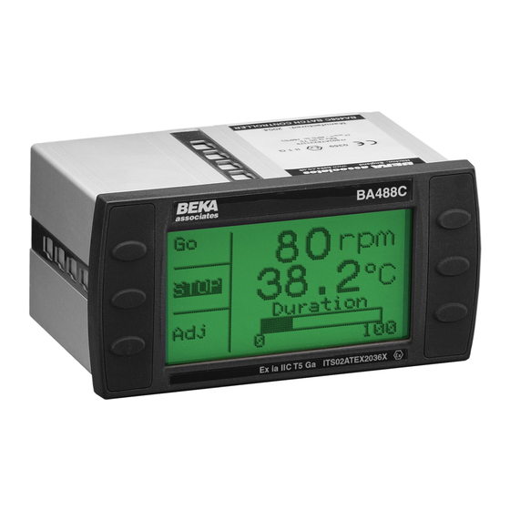
Page 3: Description
Speed increase joint between the instrument and the panel. Font 5 soft font storage The BA488C text display has been issued with an instrument’s firmware version EC-Type Examination Certificate by Notified Body established using the ‘Unit Info’... -
Page 4: Operation
When using the legacy protocol, the configuration menus are only operational between power being applied to the BA488C and the first message being received. 3.2 Modbus RTU protocol The BA488C supports Modbus RTU protocol in slave mode. - Page 5 Modbus system. Modbus protocol is described in the Serial Text Display – Modbus Guide, which is available from One variable + vertical bargraph the BEKA sales office and from the BEKA web site.
-
Page 6: Beka Protocol
Two single pole solid state outputs may be used to switch certified hazardous area loads such as sounders, beacons and valves. BEKA protocol is described in the Serial Text Display – Programming Guide which is available from the BEKA sales office and from the BEKA web site. -
Page 7: Intrinsic Safety Certification
4. INTRINSIC SAFETY CERTIFICATION This allows the BA488C to be installed in all Zones and to be used with most common industrial 4.1 ATEX certificate gases. The BA488C has been issued with EC-Type Examination Certificate ITS02ATEX2036X Notified Body Intertek Testing & Certification Ltd Special conditions for safe use in Zone 0 (ITS). -
Page 8: Switch Outputs
Clause 5.4 of IEC60079- This allows each of the BA488C switch outputs to be connected to any intrinsically safe circuit protected by a certified Zener barrier or... -
Page 9: System Design For Hazardous Area
5. SYSTEM DESIGN FOR HAZARDOUS AREAS 5.1.1 Cable length The BA488C serial text display may be powered The communications speed, type of cable and to a and communicate via a BA201 Communications lesser extent the permissible intrinsic safety cable Isolator or a MTL5051 serial data comms isolator. -
Page 10: Two Wire System
The three wire system shown in Fig 3 can power frequently used system. One or two BA488C and address up to four BA488C serial text serial text displays are connected to a BA201 in displays. If more than two displays are connected,... -
Page 11: Two Wire System
If data corruption occurs the with system certificate Ex02E2038. It employs an communication speed should be reduced. additional galvanic isolator, the MTL5025 solenoid/ alarm driver, enabling up to four BA488C serial text displays to be powered and addressed. When 5.2.2 Conditioning the MTL5051... -
Page 12: Four Wire System
5.2.5 Four wire system The four wire system which is defined by ITS System Certificate Ex02E2039 and shown in Fig 6 allows communication at higher and lower rates than the other two MTL5051 configurations. should be used for applications requiring fast display updates, or with slow data rates when long cable runs are required. -
Page 13: Switch Outputs
WARNING These switch outputs should not be used for critical safety applications such as an emergency shut down system. When the BA488C power supply is turned off or disconnected, both BA488C switch outputs will open irrespective they have been programmed. -
Page 14: Installation
Connect the panel wiring to the rear Fig 8 shows the overall dimensions of the BA488C terminal block(s) as shown in Fig 9. and the panel cutout. To achieve an IP66 seal... -
Page 15: Emc
6.3 EMC The BA488C complies with the requirements of the European EMC Directive 2004/108/EEC. specified immunity all wiring should be in screened twisted pairs. To prevent circulating currents, cable screens should only be earthed at one point in the safe... - Page 16 ‘Invalid code’ will be displayed. The BA488C is configured via four of the front When entering an access code, timeout will occur panel push-buttons. All the configuration functions and the instrument will automatically return to the...
- Page 17 When ‘On’ is selected the maximum backlight brightness will be automatically set depending Protocol upon whether a ‘Single Unit’ or ‘Multiple Unit’ BEKA, Legacy or Modbus protocol may be has been selected in the configuration menu. selected. The Legacy protocol is compatible When ‘Off’...
-
Page 18: Quick Access Menu
If an access code other than the default code 0000 has already been entered, the BA488C will request that the access code be entered. Section 7.2 explains how an access code should be entered. -
Page 20: Maintenance
Incorrect wiring between terminal clearance certificate is available. 1 and 2 of the seven way If a BA488C fails after it has been functioning connector. Terminal 1 correctly, the table shown in section 8.1 may help should be to identify the cause of the failure. -
Page 21: Accessories
9.3 Serial Text Display – Modbus Interface Guide This guide explains how to use the BA488C serial text display as a slave in Modbus RTU systems. It may be requested from the BEKA sales office or downloaded from... -
Page 22: Index
3.2, 9.3 Isolator. 2, 4.3, 5.1 MTL644 display MTL5051 serial data Backlight 5.1, 5.2, 7.1 comms isolator. 2., 4.3, 5.2 BEKA protocol MTL5025 galvanic isolator 2., 5.2.4 Cable Nonincendive Approval A2.2 Length 5.1.1, 5.2.1 Notified Body Parameters 4.4, 4.5, 5.1.1 Pattern matching 1.1, 1.2, 3... -
Page 23: Appendix 1
(RS232 or RS422) and connect the safe area communications cable to the correct terminals. 2. Apply power to the galvanic isolator(s). 3. The BA488C will display the model number and software details for a few seconds before reverting to the BEKA logo. -
Page 24: Appendix 2
Canadian installations must comply with the Canadian Electrical Code C22.2 and the BEKA Control Drawing CI480-08. A2.1 Intrinsic safety approval The BA488C is approved to the FM Class 3610 The BA488C has a T4 rating at ambient intrinsic safety standard for use in hazardous °... -
Page 38: Appendix 3
Group B ethylene Group C hydrogen Having a temperature classification of: 450°C 300°C 200°C 135°C 100°C At an ambient temperature between –40 and +60°C. Note: the guaranteed operating temperature range of the BA488C Serial Text Display is –20 to +60°C...
Need help?
Do you have a question about the BA488C and is the answer not in the manual?
Questions and answers