Table of Contents
Advertisement
Quick Links
Advertisement
Table of Contents

Summary of Contents for EUCHNER MCM-MLI Series
- Page 1 Operating Instructions Extension Module MCM-MLI... from V1.0.0...
-
Page 2: Table Of Contents
Operating Instructions Extension Module MCM-MLI... Contents About this document ..................... 3 1.1. Scope ............................3 1.1.1. Notes on older product versions ..................3 1.2. Target group ..........................3 1.3. Key to symbols ..........................3 1.4. Supplementary documents ......................3 Correct use ......................4 Description of the safety function ................4 Exclusion of liability and warranty ................. -
Page 3: About This Document
Important! Always read all documents to gain a complete overview of safe installation, setup and use of the device. The documents can be downloaded from www.euchner.com. For this purpose enter the doc. no. in the search box. 2500236-02-12/19 (Translation of the original operating instructions) -
Page 4: Correct Use
MLI device. On the unauthorized modification of system components, EUCHNER provides no warranty for function. The customer is responsible for the safe overall function, especially for the safe integration into the PROFIsafe environment. -
Page 5: General Safety Precautions
Prior to use, read the operating instructions and keep these in a safe place. Ensure the operating instructions are always available during mounting, setup and servicing. For this reason you should archive a printed copy of the operating instructions. You can download the operating instructions from www.euchner.com. 2500236-02-12/19 (Translation of the original operating instructions) -
Page 6: Function
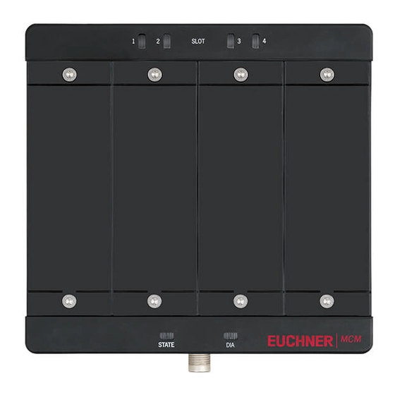
Operating Instructions Extension Module MCM-MLI... 6. Function Extension modules MCM have space for up to four submodules. In this way even more extensive control tasks can be realized. Figure 1: Extension module MCM with two operating modules and two labeling modules on one bus module MBM. 6.1. -
Page 7: Mounting
Operating Instructions Extension Module MCM-MLI... 7. Mounting 7.1. Mounting modules 7.2. Replacing modules CAUTION Risk of damage to equipment or malfunction as a result of uncontrolled machine stop. The communication within the system is interrupted by the replacement of a module, and the safe bits are reset. -
Page 8: Mounting Submodules
Operating Instructions Extension Module MCM-MLI... 7.3. Mounting submodules CAUTION Risk of damage to equipment or malfunction as a result of incorrect connection or a configuration change. Ì Only submodules of connection types P, R, E and N can be used. Check the compatibility before installation. -
Page 9: Replacing Submodules
Operating Instructions Extension Module MCM-MLI... 7.4. Replacing submodules CAUTION Risk of damage to equipment or malfunction as a result of uncontrolled machine stop. The communication within the system is interrupted by the replacement of a submodule, and the safe bits are reset. If a process is running, this situation can result in an uncontrolled stop and damage to the installation or the product. -
Page 10: Fitting And Removing Lenses And Labels For Controls And Indicators
Operating Instructions Extension Module MCM-MLI... 7.5. Fitting and removing lenses and labels for controls and indicators Fitting 90° Click! Removing Lens 8. Protection against environmental effects A lasting and correct safety function requires that the system must be protected against foreign bodies such as swarf, sand, blasting shot, etc., which can become lodged in the housing. -
Page 11: Controls And Indicators
Operating Instructions Extension Module MCM-MLI... 9. Controls and indicators 9.1. LED displays The LEDs indicate the device status and the communication status. An exact description of the indicators and faults can be found in section 11. Setup. Description Extension module MCM Combined indication Power: illuminated with correct power supply POWER/FC... - Page 12 No, must be ordered separately tion of a stacklight Module connector M12, 8-pin socket, for the connec- 157029 tion of a stacklight Connecting cable M12, 5-pin See catalog or www.euchner.com Connecting cable M12, 8-pin (Translation of the original operating instructions) 2500236-02-12/19...
-
Page 13: Setup
Operating Instructions Extension Module MCM-MLI... Setup For instructions on setup, please refer to the operating instructions for your bus module MBM. 11.1. System status table (module LEDs) If there are faults, the bit EM.E_G is set. After the fault has been rectified, it can be acknowledged using the bit EM.ACK_G. The bit EM.E_G is reset during the process. -
Page 14: System Status Table (Slot Leds)
Operating Instructions Extension Module MCM-MLI... 11.2. System status table (slot LEDs) If a fault occurs on the submodule, the bit EM.E_SM.. is set. As soon as the fault has been corrected, it is reset automatically (non-latching fault). Fault display Meaning Measures LED SLOT1 ... -
Page 15: Technical Data
Operating Instructions Extension Module MCM-MLI... 13. Technical data NOTICE If a data sheet is included with the product, the information on the data sheet applies. Parameter Value Housing material Fiber glass reinforced plastic Die-cast zinc, nickel-plated Dimensions See dimension drawing Weight Approx. -
Page 16: Service
Loss of the safety function because of damage to the device. In case of damage, the affected module must be replaced completely. Only accessories or spare parts that can be ordered from EUCHNER may be replaced. Regular inspection of the following is necessary to ensure trouble-free long-term operation: Ì... -
Page 17: Declaration Of Conformity
Operating Instructions Extension Module MCM-MLI... 16. Declaration of conformity 2500236-02-12/19 (Translation of the original operating instructions) - Page 18 Operating Instructions Extension Module MCM-MLI... (Translation of the original operating instructions) 2500236-02-12/19...
- Page 19 Operating Instructions Extension Module MCM-MLI... 2500236-02-12/19 (Translation of the original operating instructions)
- Page 20 Edition: 2500236-02-12/19 Title: Operating Instructions Extension Module MCM-MLI... and from V1.0.0 (Translation of the original operating instructions) Copyright: © EUCHNER GmbH + Co. KG, 12/2019 Subject to technical modifications; no responsibility is accept- ed for the accuracy of this information.


Need help?
Do you have a question about the MCM-MLI Series and is the answer not in the manual?
Questions and answers