
Related Manuals for 3Com 3C16080


Summary of Contents for 3Com 3C16080
- Page 1 3C16080 Part No. DUA1608-0AAA01 Published May 1997 ® UPER TACK DVANCED ANAGEMENT UIDE ODULE...
- Page 2 Santa Clara, California 95052-8145 ©3Com Ireland 1997. All rights reserved. No part of this document may be reproduced in any form or by any means or used to make any derivative work (Such as translation, transformation, or adaptation) without permission from 3Com Ireland.
-
Page 3: Table Of Contents
ONTENTS BOUT UIDE Introduction Conventions NTRODUCTION Networking Terminology NSTALLATION The SuperStack II Advanced RPS Management Module Before You Start Installing the Management Module ONFIGURING Before You Start Local Configuration Command Line Interface System Login Commands Changing the Configuration Fields Software Update Exiting the Configuration Program ANAGING Connecting to the Network... - Page 4 Console Port Pin Out MDI 10BaseT RJ-45 Connector Pin Out ROUBLESHOOTING ECHNICAL UPPORT On-line Technical Services 3Com Bulletin Board Service Access by Modem Access by ISDN World Wide Web Site ThreeComForum on CompuServe 3ComFacts Automated Fax Service Support from Your Network Supplier...
-
Page 5: About This Guide
BOUT Introduction This guide describes how to install and use the SuperStack Advanced RPS Management Module. Each procedure is outlined in a series of steps. These procedures are written primarily for network supervisors who are responsible for installing and configuring the Management Module. You should also be familiar with PC hardware and software, and have a basic understanding of your network. - Page 6 BOUT UIDE Convention Description “Enter” vs. “Type” When the word “enter” is used in this guide, it means to type something, then press the [Return] or [Enter] key. Do not press the [Return] or [Enter] key when the instruction simply says “type”. Text represents as This typeface is used to represent displays that appear on screeen display...
-
Page 7: The Superstack Ii Advanced Rps Management Module
NTRODUCTION In the modern business environment, communication and sharing information is crucial. With computer networks becoming larger and more complex, a constant power supply is vital to the operation of your organization. A Redundant Power Supply (RPS) provides a highly reliable resilient power supply to maintain network integrity. - Page 8 1: I HAPTER NTRODUCTION Simple Network Management Protocol (SNMP) is a protocol that controls how a management station gains information from a device. SNMP is composed of three areas: A set of rules that define how a management station can communicate with a device.
-
Page 9: Installation
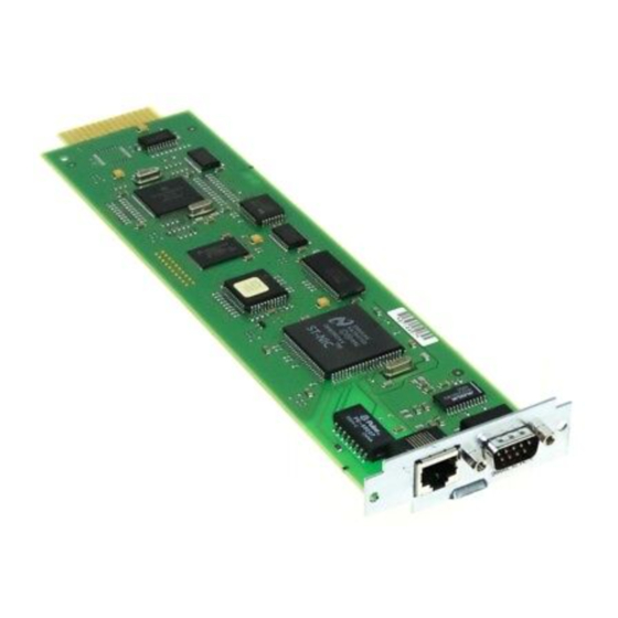
NSTALLATION This chapter describes the SuperStack II Advanced RPS ® Management Module and how to install the module in the SuperStack II Advanced RPS. The SuperStack II Advanced RPS Management Module The Management Module plugs directly into your SuperStack II Advanced RPS chassis. - Page 10 2: I HAPTER NSTALLATION Figure 2-1 Ethernet Module Connections DUA1608-0AAA01...
-
Page 11: Before You Start
Before You Start The SuperStack II Advanced RPS Management Module will only operate with the SuperStack II Advanced RPS. You will need a 10BASE-T cable for connection to your Ethernet network and a serial cable to configure your Management Module. You may also use the serial cable and for management via a modem, if required. - Page 12 2: I HAPTER NSTALLATION Figure 2-2 Removing the Blanking Plate on Advanced RPS 2 Slide the Management Module into the open slot and secure with the screws provided. Make sure the RJ-45 connector is located on the lefthand side when looking at the rear panel. Figure 2-3 Sliding the Module into the Advanced RPS DUA1608-0AAA01...
-
Page 13: Configuring The Management Module
The CLI provides initial configuration of the Management Module. To manage the Superstack II Advanced RPS, you can use 3Com Transcend or another SNMP network manager. Before You Start If your network has a BootP server configured to respond, the Management Module will solicit its addresses automatically. -
Page 14: Local Configuration
3 Press [Return]. The following login prompt should appear (see System Login on page 3-4 for more details). SuperStack II Advanced RPS <software version> Copyright © 3Com Ireland 1997. Login: If the login prompt does not appear, press [Return] and make sure the Management Module is properly connected to the Advanced RPS, as described in “Installing the Management Module”... - Page 15 If you still do not see the login prompt, check the following conditions: Check the communications settings of the terminal you are using. It should be set to 9600 baud, no parity, 8 bits, and 1 stop bit. If the serial configuration is correct, check the cable between the module and terminal to be sure all connections are secure.
-
Page 16: Command Line Interface
System Login To activate the CLI, press [Return]. You are presented with the title screen, showing the product name, the 3Com copyright and the software version number, and a login: prompt, as shown below: SuperStack II Advanced RPS <software version>... -
Page 17: Commands
Commands The available commands are described in more detail. Help Usage: Abbreviation: Description: IP Address Usage: Abbreviation: Description: Value takes effect from: Value retained during Power cycle: DUA1608-0AAA01 Command Line Interface help ? or HE Lists all of the available commands, as below: HElp IPAddress... - Page 18 3: C HAPTER ONFIGURING Password Usage: Abbreviation: Description: Value takes effect from: Value retained during Power cycle: Display Usage: Abbreviation: Description: DUA1608-0AAA01 ANAGEMENT ODULE PASSWD None Change the password for the current user. The CLI prompts you for the new password which, when typed in, is concealed by asterisks (*).
-
Page 19: Subnet Mask
Subnet Mask Usage: Abbreviation: Description: Value takes effect from: Value retained during Power cycle: Default Router Usage: Abbreviation: Description: Value takes effect from: Value retained during Power cycle SLIP Address Usage: Abbreviation: Description: Value takes effect from: Value retained during Power cycle: DUA1608-0AAA01 Command Line Interface... -
Page 20: Factory Defaults
3: C HAPTER ONFIGURING SLIP Mask Usage: Abbreviation: Description: Value takes effect from: Value retained during Power cycle: Factory Defaults Usage: Abbreviation: Description: Value takes effect from: Value retained during Power cycle: DUA1608-0AAA01 ANAGEMENT ODULE slipmask a.b.c.d SLIPM Enters the SLIP mask for the device. Reset Command factorydefaults FACT... -
Page 21: Flow Control
Flow Control Usage: Abbreviation: Description: Value takes effect from: Value retained during Power cycle: Community String Usage: Abbreviation: Description: Value takes effect from: Value retained during Power cycle: DUA1608-0AAA01 Command Line Interface FLOwctrl ON or OFF Change the Console data flow signal to ON or OFF. -
Page 22: Trap Destination
3-10 3: C HAPTER ONFIGURING Reset Usage: Abbreviation: Description: Value retained during Power cycle: Trap Destination Usage: Abbreviation: Description: Value takes effect from: Value retained during Power cycle: Logout Usage: Abbreviation: Description: DUA1608-0AAA01 ANAGEMENT ODULE RESET None. Resets the Management Module. Any changed network parameters are then implemented as described previously. -
Page 23: Changing The Configuration Fields
Changing the Configuration Fields The first fields you must configure depend on the method of network connection that you are using. For Ethernet, you need to configure the IP address, Subnet mask and Default Router. For SLIP, you need to configure the SLIP address and SLIP mask. To change the value of a setup option, enter the command (or abbreviation) followed by the new value. - Page 24 3-12 3: C HAPTER ONFIGURING ANAGEMENT ODULE Subnet Mask To change the Subnet mask value, type SUB followed by a space and the Subnet mask value. Use the format a.b.c.d, where a, b, c and d are numbers between 0 and 255. If you type a number that is not in this range, an error message appears.
- Page 25 Command Line Interface 3-13 SLIP Address To change the SLIP address, type SLIPA followed by a space and the SLIP address assigned to the Management Module. Use the format a.b.c.d, where a, b, c and d are numbers between 0 and 255. If you type a number that is not in this range, an error message appears.
-
Page 26: Software Upgrade
If a new version is released, instructions for downloading it to the Module will be contained in the software. The latest version of the software can be found on a 3Com bulletin board or the World Wide Web page, details of which are in Appendix C, “Technical Support”. -
Page 27: Managing Your Advanced Rps
Be sure you have the appropriate cables and connectors, as described in “Before You Start” on page 2-3. Connecting to the Network To connect the Management Module to the network: 1 Plug one end of a twisted-pair cable into the RJ-45 port on the Management Module. - Page 28 4: M HAPTER ANAGING Managing Your Advanced RPS For day-to-day management of the SuperStack system, we recommend Transcend Enterprise Manager. For more details on this and other products, please contact your supplier. DUA1608-0AAA01 DVANCED II Advanced RPS ®...
-
Page 29: Technical Specifications
ECHNICAL Standards The SuperStack designed to comply with the following standards: Safety Environmental EN 60068 * Category 5 shielded cables are required to meet the Class B limits of this standard. The use of unscreened cables (category 3 or 5) complies with the Class A limits. -
Page 30: Console Port Pin Out
Appendix A: Technical Specifications Console Port Pin Out Table A-2 Pin Number Figure A-1 The console port has the same configuration as an IBM PC Com port. Only the TD, RD and ground pins need be connected to use the CLI from a terminal. -
Page 31: Mdi 10Baset Rj-45 Connector Pin Out
MDI 10BASE-T RJ-45 Connector Pin Out Table A-3 RJ-45 Connector Pin Out Contact Figure A-2 RJ-45 Connector Numbering MDI 10BASE-T RJ-45 Connector Pin Out MDI Signal No connection No connection No connection No connection DUA1608-0AAA01... - Page 32 Appendix A: Technical Specifications Cabling 10BASE-T Cabling Figure A-3 Serial Cable Figure A-4 10BASE-T Cabling Pin Numbering for Serial Cable DUA1608-0AAA01...
- Page 33 Cabling Examples of null modem cables you can use follow. Figure A-5 Null Modem Cabling Example for 9 Pin Port Figure A-6 Null Modem Cabling Example for 25 Pin Port DUA1608-0AAA01...
- Page 34 Appendix A: Technical Specifications DUA1608-0AAA01...
-
Page 35: Roubleshooting
ROUBLESHOOTING Use the following troubleshooting chart to help you solve any problems that may occur with the SuperStack Management Module. Problem The Management Module does not initialize Login prompt does not appear ® Possible Cause Corrective Action Bad cable Verify cable connections at connection the Management Module Incorrect cable. - Page 36 B: T PPENDIX ROUBLESHOOTING Problem Management Module does not respond to SNMP Get requests, but does respond to Pings. DUA1608-0AAA01 Possible Cause Corrective Action Wrong community To verify that the community namestring being name is strings used. The aremismatched, connect a Get-community name terminal to the module (see community strings...
-
Page 37: C Technical Support
For the very latest details, we recommend you access 3Com Corporation’s World Wide Web site as described below. On-line Technical Services 3Com offers worldwide product support seven days a week, 24 hours a day, through the following on-line systems: 3Com Bulletin Board Service (3ComBBS) -
Page 38: Access By Isdn
3ComForum on CompuServe 3ComForum is a CompuServe-based service containing patches, software, drivers, and technical articles about all 3Com products, as well as an interactive forum for technical questions. To use 3ComForum, you need a CompuServe account. DUA1608-0AAA01... -
Page 39: 3Comfacts Automated Fax Service
3ComFacts Automated Fax Service 3Com Corporation’s interactive fax service, 3ComFacts, provides data sheets, technical articles, diagrams, and troubleshooting instructions on 3Com products 24 hours a day, seven days a week. Call 3ComFacts using your touch-tone telephone. International access numbers are:... -
Page 40: Support From Your Network Supplier
If you are unable to receive support from your network supplier. technical support contracts are available from 3Com. In the U.S. and Canada, call (800) 876-3266 for customer service. If you are outside the U.S. or Canada, contact your local 3Com sales office to find your authorized service provider: Country... -
Page 41: Returning Products For Repair
* These numbers are toll-free Returning Products for Repair A product sent directly to 3Com for repair must first be assigned a Return Materials Authorization (RMA) number. A product sent to 3Com without an RMA number will be returned to the sender unopened, at the sender’s expense. - Page 42 C: T PPENDIX ECHNICAL UPPORT DUA1608-0AAA01...
-
Page 43: Limited Warranty
SOFTWARE: 3Com warrants that the software programs licensed from it will perform in substantial conformance to the program specifications therefore for a period of ninety (90) days from the date of purchase from 3Com or its Authorized Reseller. 3Com warrants the magnetic media containing software against failure during the warranty period. - Page 44 STANDARD WARRANTY SERVICE: Standard warranty service for hardware products may be obtained by delivering the defective product, accompanied by a copy of the dated proof of purchase, to 3Com’s Corporate Service Center or to an Authorized 3Com Service Center during the applicable warranty period.
-
Page 45: Vcci Statement
FEDERAL COMMUNICATIONS COMMISSION RADIO AND TELEVISION INTERFERENCE STATEMENT FOR CLASS A DEVICES This equipment has been tested and found to comply with the limits for Class A digital devices, pursuant to part 15 of the FCC Rules. These limits are designed to provide reasonable protection against harmful interference in a residential installation.
Need help?
Do you have a question about the 3C16080 and is the answer not in the manual?
Questions and answers