Table of Contents
Advertisement
Advertisement
Table of Contents

Related Manuals for Qu-Bit Electronix Data Bender


Summary of Contents for Qu-Bit Electronix Data Bender
- Page 1 Data Bender...
-
Page 2: Table Of Contents
Contents Description Specifications Installation Marked Diagram Core Control Overview 1. Time ........Internal Clock Mode . - Page 3 Gate Behaviors ....... . Stereo Behavior ....... . Corrupt As Reset .
-
Page 4: Description
Description Data Bender is a circuit bent digital audio buffer. It is inspired by the ways in which audio equipment can fail. The sounds of skipping CDs, software bugs, and defective tape machine playback are all accessible. The 96kHz, 24-bit audio buffer can hold over a minute of stereo audio, providing a sonic canvas capable of infinite surprises and discovery. -
Page 5: Specifications
Specifications Depth: 28mm Width: 14HP Current Consumption: • +12V: 58mA • -12V: 60mA • +5V: 0mA... -
Page 6: Installation
Installation T o install, locate 14HP of space in your Eurorack case and confirm the positive 12 volts and negative 12 volts sides of the power distribution lines. Plug the connector into the power distribution board of your case, keeping in mind that the red band corresponds to negative 12 volts. -
Page 7: Marked Diagram
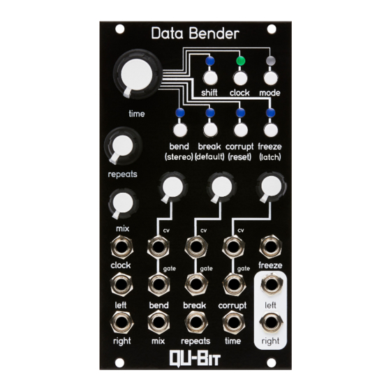
Marked Diagram... -
Page 8: Core Control Overview
Core Control Overview 1. Time Time sets the sample period for incoming audio to be processed. This is the rate at which a new audio buffer is acquired for processing and manipulation. Switch between Internal and External Clock modes by pressing the clock button. The buffer space located outside of the current section set by time is written to in the back- ground so that some fairly recent audio is always in the buffer when time is changed. -
Page 9: Repeats
2. Repeats Repeats divides the primary buffer into smaller subsections of audio. These will be heard as repeated pieces of the recorded audio buffer. Several parameters within the module will control which section of the buffer is repeating as well as modify this control itself. The higher the knob is increased the more divisions of the buffer are created, and the “faster”... -
Page 10: Destroy
Destroy Controls an amount of Soft saturation and hard clipping applied to the signal. The first half of the knob softly saturates, and the second half introduces absolute devasta- tion. Caution: this gets loud if using with signals that aren’t modular level to begin with 7. -
Page 11: Mode
If the module has not received an external clock for at least four beats (one measure) at the last recorded clock rate, the LED will illuminate a DIM white to indicate that there is no clock source present. While there is no clock source, the clock will continue to run at the last rate until a new clock pulse is detected. -
Page 12: Macro Mode
Macro mode is a set of 3 controls that have automated parameters based on the clock settings. Set the knobs where you like them and let the Data Bender bend your data for you. 4. Bend Bend provides manipulations that are inspired by the tape medium and its associated play- back machines. -
Page 13: Micro Mode
At the lowest settings, it will only have a slight chance to add additional repeats, or move to a new sub-section of the buffer At the maximum settings, it can jump to any sub-section of the buffer, and has a high like- lihood to do so. -
Page 14: Silence
Silence When the LED is illuminated, the control acts as a duty-cycle for the amount of silence introduced. On the far left of the knob, there will be no silence. On the far right of the knob, 90% of the playback buffer will be replaced with silence. Edit Functions Glitch Windowing Using SHIFT + TIME you can scale an amount of windowing to be applied to the individual... - Page 15 • Bend disabled • Break disabled • Freeze disabled • Mode to Macro Mode • Stereo behavior to shared mode. • Gates to Latching • Break Jack set to primary function (not reset/sync). • Freeze button behavior to latching mode Gate Behaviors While holding shift, the Freeze LED will indicate whether the gates are configured as mo- mentary or latching.
- Page 16 This can be useful for synchronizing with a DAW or manually restarting the buffer, and ran- domizing Macro mode controls when running with a slow internal clock. In internal clock mode, this will resync the internal clock immediately, causing new audio to load into the buffer, possibly resulting in silence during certain bend/break settings.
Need help?
Do you have a question about the Data Bender and is the answer not in the manual?
Questions and answers