Advertisement
User manual
CALIBRATING THE TESTER
Before you can start testing components, you will have to calibrate the tester. What you'll
need is a capacitor with a capacity between 100nF and 20µF.
Then follow the calibration procedure below:
1. Connect the 3 probes together.
2. Press the button on the tester and immediately press it again if you see "Selftest mode"
on the screen. If successful, you should see "R0=".
3. When you "isolate Probes" appears on the screen, disconnect all the probes.
4. When you see "1 -||-3 > 100nF" appear on the screen, connect the capacitor to probes 1
and 3.
5. After a while, the calibration should end with success.
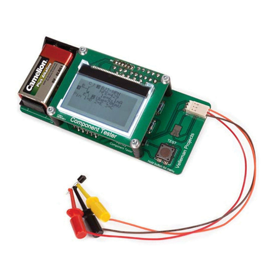
CONNECTING A COMPONENT
Connecting a component is easy; simply connect the leads of a component to the
connectors. The order/polarity doesn't matter because the tester will figure this out on its
own.
When testing a component, make sure that you do not touch the component during the test
and that it is placed on a non-conductive pad.
EXTRA FEATURES
You can access the extra features by long pressing the button to enter the menu.
f-Generator
By using the additional "f-Generator" (frequency generator) function, the selectable
frequencies can be
switched with key presses. With a long key press (> 0.8s) you will stop the frequency
generator and
return to the function menu.
10-bit PWM
The additional "10-bit PWM" (Pulse Width Modulation) function generates a fixed
frequency with
selectable pulse width at the pin TP2. With a short key press (< 0.5s) the pulse width is
increased by 1%, with a longer key press the pulse width is increased by 10%. If 99%
is overstepped, 100% is subtracted from the result. You can exit this mode with a very long
key press (> 1.3s).
Advertisement
Table of Contents

Subscribe to Our Youtube Channel
Related Manuals for Velleman K8115


Summary of Contents for Velleman K8115
- Page 1 User manual CALIBRATING THE TESTER Before you can start testing components, you will have to calibrate the tester. What you'll need is a capacitor with a capacity between 100nF and 20µF. Then follow the calibration procedure below: 1. Connect the 3 probes together. 2.
- Page 2 C+ESR@TP1:3 The additional "C+ESR@TP1:3" function selects a stand-alone capacity measurement and an ESR (Equivalent Series Resistance) measurement at the test pins TP1 and TP3. Capacities of 2µF up to 50mF can be measured. In most cases, the capacitor can be measured "in circuit" without previous disassembling because the measurement voltage is only about 300mV.
Need help?
Do you have a question about the K8115 and is the answer not in the manual?
Questions and answers