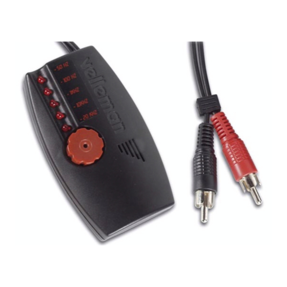
Summary of Contents for Velleman k8065
- Page 1 Total solder points: 109 Difficulty level: beginner 1 advanced POCKET AUDIO GENERATOR K8065 ILLUSTRATED ASSEMBLY MANUAL H8065IP-1...
-
Page 3: Specifications
Features & Specifications Features: Microprocessor technology Digital waveform generation Specifications: Sine wave: 50Hz, 100Hz, 1KHz, 10KHz, 20KHz Burst: 50Hz, 100Hz, 1KHz Burst mode: 20ms ON, 500ms OFF Noise: 32-bit digital noise Output level (10Kohm): 0 to 775mV (0dB) Outputs: 2 x RCA (cinch) Power supply: 2 x CR2016 or 2 x CR2025 battery (excl.) Dimensions: 86 x 50 x 25mm (3.4"... - Page 4 Assembly hints 1. Assembly (Skipping this can lead to troubles ! ) Ok, so we have your attention. These hints will help you to make this project successful. Read them carefully. 1.1 Make sure you have the right tools: • A good quality soldering iron (25-40W) with a small tip.
- Page 5 AXIAL COMPONENTS ARE TAPED IN THE CORRECT MOUNTING SEQUENCE ! REMOVE THEM FROM THE TAPE ONE AT A TIME ! You will find the colour code for the resistances and the LEDs in the HALG (general manual) and on our website: http://www.velleman.be/common/service.aspx...
- Page 6 Construction 1. Jumper 4. Metal film resistors 7. Capacitors. R... C... C1 : 15pF (15) : 20K (2 - 0 - 0 - 2 - 1) C2 : 15pF (15) R14 : 10K (1 - 0 - 0 - 2 - 1) 2.
-
Page 7: Slide Switch
Construction 9. Slide switch. 12. Vertical metal film resistors 13. Vertical resistors R... R... R16 : 1K5 (1 - 5 - 2 - B) R1 : 20K (2 - 0 - 0 - 2 - 1) R18 : 1K5 (1 - 5 - 2 - B) R2 : 20K (2 - 0 - 0 - 2 - 1) 10. -
Page 8: Push Button
Construction 16. LEDs. Watch the polarity! COLOR= 2...5 LD1 : 3mm Red Axis of a LD2 : 3mm Red rotary switch. LD3 : 3mm Red LD4 : 3mm Red LD5 : 3mm Red LD... CATHODE 17. Push button. 18. IC. Watch the position of the notch! solderside SW... - Page 9 Assembly 19. Assembly Close the enclosure with the 2 supplied screws. Fig. 1.0 Drill two Ø3mm holes in the housing according to figure 1.0. The RCA cable will run through them. signal shielding 3mm drill. Solder the signal wires or the RCA cable to the 'OUT' terminal on the PCB (see figure 2.0).
- Page 10 Assembly Insert two CR2025 or two CR2016 batteries into the battery holder. Mind the polarity!, see figure 3.0 Mount all parts and close the housing by means of the enclosed screws, see figure 4.0. BEWARE: Do not forget to feed the RCA cable through the two holes in the housing.
- Page 11 Assembly Now stick the enclosed stickers to the housing (see fig. 5.0) Fig. 5.0...
- Page 12 Instructions 20. Instructions Front side Back side 1. On/Off switch 2. Frequency/mode select button 3. Frequency/mode indicators 4. Level adjust 5. RCA outputs Selecting a frequency : press (2) repeatedly until the LED indication displays the right frequency. Toggle between normal and burst mode* : Hold selector (2) for a few seconds and then release it. The indication LED flashes 3x for the burst mode and only once for the normal mode.
- Page 13 Instructions Example : 100Hz burst signal : 100Hz. ‘Noise' mode : hold (2) and activate the device, then release button (2). The ‘noise’ mode is indicated by the two bottom LEDs. Noise output...
- Page 14 21. PCB layout.
- Page 15 Diagram 22. Diagram 3V CR2016 X2 R1 20K 1N4148 100nF SW SLIDE LC R2 20K C1 15pF RA5/T1CKVOSC1/CLKN R4 20K 20MHz RA4/T1G/OSC2/CLKOUT C2 15pF R5 20K RA3/MCLR/Vpp R16 1K5 RA0/CIN+/ICSPDAT SW KRS0611 C4 47µF R6 20K R17 1K5 RA1/CIN-/ICSPCLK BC557 R18 1K5 RA2/COUT/TOCKI/INT R7 20K...
- Page 16 VELLEMAN Components NV Legen Heirweg 33 9890 Gavere Belgium Europe www.velleman.be www.velleman-kit.com Modifications and typographical errors reserved © Velleman Components nv. H8065IP - 2004 - ED1 (rev.1) 5 4 1 0 3 2 9 3 2 7 5 5 2...


Need help?
Do you have a question about the k8065 and is the answer not in the manual?
Questions and answers