Advertisement
Quick Links
Advertisement

Subscribe to Our Youtube Channel
Related Manuals for Velleman k2601


Summary of Contents for Velleman k2601
- Page 1 Total solder points: 38 Difficulty level: beginner 1 advanced STROBOSCOPE K2601 Features Power supply : 220-240VAC Power consumption : 3-10W Flash frequency : 2-20Hz Nominal flash energy : 11Ws Life-time : typical 800.000 flashes ILLUSTRATED ASSEMBLY MANUAL H2601IP-1...
- Page 2 VELLEMAN NV Legen Heirweg 33 9890 Gavere Belgium Europe www.velleman.be www.velleman-kit.com...
-
Page 3: Features And Specifications
Features & Specifications Features Dynamic effect for disco’s and party’s Imitate lightning strikes - great for theatrical productions Photographic special effects Use as warning or hazard light Great to attract attention ! Your own unique application Specifications Power supply : 220-240VAC Power consumption : 3-10W Flash frequency : 2-20Hz Nominal flash energy : 11Ws... -
Page 4: Assembly Hints
Assembly hints 1. Assembly (Skipping this can lead to troubles ! ) Ok, so we have your attention. These hints will help you to make this project successful. Read them carefully. 1.1 Make sure you have the right tools: • A good quality soldering iron (25-40W) with a small tip. - Page 5 Assembly hints 1.3 Soldering Hints : 1- Mount the component against the PCB surface and carefully solder the leads 2- Make sure the solder joints are cone-shaped and shiny 3- Trim excess leads as close as possible to the solder joint REMOVE THEM FROM THE TAPE ONE AT A TIME ! DO NOT BLINDLY FOLLOW THE ORDER OF THE COMPONENTS ONTO THE TAPE.
-
Page 6: Trigger Coil
Construction 1. Diac. 4. PCB tabs 7. Capacitor C3 : 100nF/250Vac D... DI1 : DO35 Resistor. 2. Diodes. Watch the polarity ! 8. Electrolytic Capacitors Watch the polarity ! R... D1 : 1N4007 C1 : 10µF/350V !!! D... D2 : 1N4007 CATHODE C2 : 10µF / 50V D3 : 1N4007... -
Page 7: Flash Tube
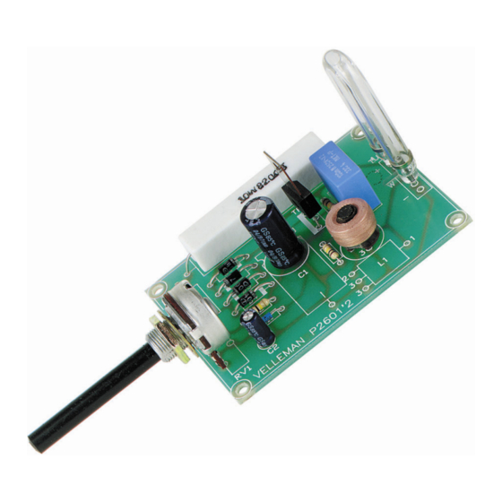
Construction 10. Potentiometer RV1 : 470K 11. Flash tube. TU B E Tube Watch the position of the dot! - Page 8 Connection example 12. Connection example...
- Page 9 13. PCB...
- Page 10 Diagram 14. Diagram 820/10W D1...D4 AC POWER 1N4007 100K 100K TUBE BT136 S6049 470K TRI1 10u/350V 100n/400V 100K TC-6...
- Page 12 Modifications and typographical errors reserved - © Velleman nv. H2601IP - 2011 - ED1_rev1 5 4 1 0 3 2 9 2 9 1 0 1 3...
Need help?
Do you have a question about the k2601 and is the answer not in the manual?
Questions and answers