
Subscribe to Our Youtube Channel
Related Manuals for 3Com OfficeConnect 3CDSG8


Summary of Contents for 3Com OfficeConnect 3CDSG8
-
Page 1: User Guide
® ® 3Com OfficeConnect Managed Gigabit Switch User Guide 3CDSG8 www.3Com.com Part Number 10016799 Rev. BA Published July 2008... - Page 2 MA 01752-3064 3Com Corporation reserves the right to revise this documentation and to make changes in content from time to time without obligation on the part of 3Com Corporation to provide notification of such revision or change. 3Com Corporation provides this documentation without warranty, term, or condition of any kind, either implied or expressed, including, but not limited to, the implied warranties, terms or conditions of merchantability, satisfactory quality, and fitness for a particular purpose.
-
Page 3: About This Guide
BOUT This guide provides information about the Web user interface for the 3Com® OfficeConnect Managed Gigabit Switch. The Web interface is a network management system that allows you to configure, monitor, and troubleshoot your switch from a remote web browser. The Web interface web pages are easy-to-use and easy-to-navigate. -
Page 4: Intended Audience
Most user guides and release notes are available in Adobe Acrobat Reader Portable Document Format (PDF) or HTML on the 3Com Web site: • ________________________________________________________________ Table 1 lists conventions that are used throughout this guide. -
Page 5: Table Of Contents
Setting Up Web Interface Management ... 14 Default Users and Passwords... 15 Upgrading the Software Using the CLI ... 16 Accessing the Switch using the 3Com Detect Application... 16 INSTALLING THE SWITCH ... 18 Important Safety Information ... 18 Positioning the Switch... 19 Supplying Power to the Switch... - Page 6 3Com Network Management ... 65 Device Specifications and Features... 68 Pin-Outs ... 73 3Com CLI Reference Guide... 76 Troubleshooting ... 86 Obtaining Support for Your 3Com Product... 89 Regulatory Notices... 94 FCC STATEMENT ... 94 INFORMATION TO THE USER ... 94 ICES STATEMENT... 94...
-
Page 7: Getting Started
TARTED This chapter contains introductory information about the 3Com® OfficeConnect Managed Gigabit Switch (hereafter called the Switch) and how they can be used in your network. It covers summaries of hardware and software features and also the following topics: • About the OfficeConnect Managed Gigabit Switch •... -
Page 8: Summary Of Hardware Features
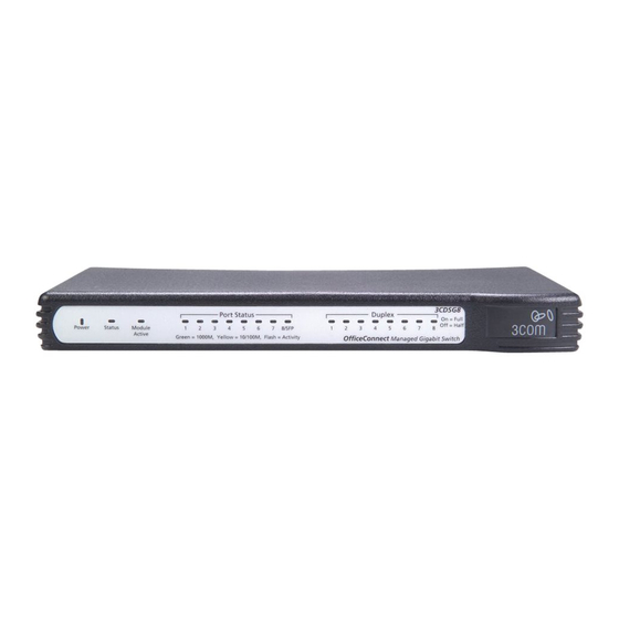
________________________________________________________________ LED Status Indicators The OfficeConnect Managed Gigabit Switch provides LED indicators on the front panel for your convenience to monitor the switch. Table 2 describes the meanings of the LEDs. Table 2 Description of the LEDs of the OfficeConnect Managed Gigabit Switch... -
Page 9: System Specifications
8/SFP Duplex Mode Duplex ________________________________________________________________ System Specifications Table 3 contains the system specifications of the OfficeConnect Managed Gigabit series switch. Table 3 System specifications of the Switch Specification Switch OfficeConnect Managed Gigabit 3CDSG8 Physical dimensions 225 x 135 x 27 mm (8.9 x 5.3 x 1.06 in.) Weight (Unpackaged) 0.57 kg (1.25 lb) -
Page 10: Installing The Switch
________________________________________________________________ Installing the Switch This section contains information that you need to install and set up your 3Com switch. WARNING: Safety Information. Before you install or remove any components from the Switch or carry out any maintenance procedures, you must read the 3Com Switch Family Safety and Regulatory Information document enclosed. -
Page 11: Automatic Ip Configuration Using Dhcp
To manage your switch, you need to use Web Interface Management. In addition, you can use the Command Line Interface through the Console port for basic operations of the switch, including viewing the IP address, upgrading the switch firmware and more. Refer to the “3Com CLI Reference Guide” in Chapter 16... -
Page 12: Manual Ip Configuration
You can access the switch through the Console port to manually set the IP address, or to view the IP address that was assigned automatically (for example, by a DHCP server). For more information about the CLI, refer to “3Com CLI Reference Guide” on page 77. Connecting to the Console Port This section describes how to connect to your switch through the Console port. - Page 13 Managed Gigabit Switch takes approximately 30 seconds to boot. Manually set the IP Address using the Console Port You are now ready to manually set up the switch with IP information using the command line interface. You need to have the following information: •...
-
Page 14: Setting Up Web Interface Management
Address 192.168.1.1 > The initial set up of your switch is now complete and the switch is ready for you to set up your chosen management method. See “Methods of Managing a Switch” on page 11. For more information about the CLI, refer to “3Com CLI Reference Guide” on page 77. -
Page 15: Web Management Over The Network
If you get an error message, check that your IP information has been entered correctly and the switch is powered up. 4. Open your web browser and enter the IP address of the switch that you wish to manage in the URL locator, for example, in the following format: http://xxx.xxx.xxx.xxx... -
Page 16: Upgrading The Software Using The Cli
The 3Com Managed Gigabit Switch CD-ROM contains in addition to the documentation the 3Com Detect Application. To use 3Com Detect to connect to the web interface of your Switch, do the following: 1. On the computer that is connected to your Switch (either directly or on a network that is on the same subnet), insert the CD-ROM into it’s CD drive. - Page 17 Once installed, the 3Com Detect Application can be accessed from the Windows Start/Programs list. When the 3Com Detect application starts, you will be see the Welcome Screen (Figure 2). Figure 2: 3Com Detect Welcome Screen 2. If the computer has multiple network adapters, select the adapter that connects the computer to the network or Switch, click “Next”.
-
Page 18: Installing The Switch
Por favor, antes de manusear o produto, leia cuidadosamente as instruções de segurança encontradas no Manual Support and Safety Information incluido no produto. Este manual pode ser encontrado no CD-ROM incluido com o seu switch ou no site da 3Com: www.3Com.com Viktig säkerhets information Vänligen hänför till säkerhets informationen som är inkluderad med denna produkt i Support... -
Page 19: Positioning The Switch
Le rogamos lea y siga atentamente las instrucciones indicadas en el manual de seguridad del Support and Safety Information, incluido en este producto. Puede encontrar el manual en el CD- ROM adjunto a su switch. Alternativamente lo puede bajar de la web de 3Com: www.3Com.com Istotne informacje dot. -
Page 20: Supplying Power To The Switch
2. Plug the power adapter into a power outlet. When the Switch is powered on, the Power LED lights up. If the Power LED does not light up, check the power supply connections including another mains outlet if appropriate. If the Power LED is still not lit it is likely that the power adapter is faulty. -
Page 21: Using Sfp Transceivers
3Com network supplier If POST fails, try the following: • Power off the Switch, and then power it on again. Check the Status LED and see if POST was successfully completed. • Restore the default configuration the Switch. Refer to the CLI commands appendix for instructions on using the System Restore Default command •... - Page 22 To access the latest list of approved SFP transceivers for the Switch on the 3Com Web site, enter this URL into your Internet browser: http://www.3Com.com 3Com recommends using 3Com SFPs in the Switch. If you insert an SFP transceiver that is not supported, the Switch will not recognize it.
-
Page 23: Performing Spot Checks
At frequent intervals, you should visually check the Switch. Regular checks can give you an early warning of a possible failure; any problems can then be attended to when there will be least effect on users. 3Com recommends periodically checking the cabling, including the power adapter and it’s connections. -
Page 24: Status
STATUS 3.1 System Information This page provides an overview of the configuration of the switch. There are five different tables on this page: • System Identity - Displays general information about the switch. • Address Information - Displays the IP Address configuration of the switch. -
Page 25: System Identity
Management VLAN and MAC Address are fixed during manufacture and are provided here for information. 3.1.3 Port Information This table contains one row for each port on the switch. Each row is divided into eight columns as follows: • Port - The front-panel port number. -
Page 26: Vlan Information
You can display statistics on network traffic from the ports. These statistics can be used to identify potential problems with the switch (such as a faulty port or unusually heavy loading). All values displayed have been accumulated since the last system reboot, but can be reset to zero by clicking the CLEAR button. - Page 27 Status them from being deliverable to a higher-layer protocol. The total number of packets that higher-level protocols Transmitted Multicast requested be transmitted, and which were addressed to a multicast Packets address at this sub-layer, including those that were discarded or not sent.
- Page 28 The total number of good frames received that were directed to the Broadcast Frames broadcast address. Note that this does not include multicast packets. CRC/Alignment Errors The number of CRC/alignment errors (FCS or alignment errors). The total number of frames received that were longer than 1518 Oversize Frames octets (excluding framing bits, but including FCS octets) and were otherwise well formed.
-
Page 29: System
This page allows you to change the System Name, System Location, and System Contact. The System Name is displayed on the Login page, and the SYSTEM > Information page. • System Name - The name of the switch. The System Name can be up to 24 characters long. -
Page 30: Ip Address
IP Address. Note: If you change the IP address used by the switch you will lose contact with this Web Management-Interface and may have to change the IP address on your PC to reconnect. -
Page 31: Password
System • APPLY - Updates the switch configuration. No changes are made to the configuration until this button is pressed. • CANCEL - All changes made to the page are discarded and the switch configuration remains unchanged. 4.3 Password This page allows you to change the password that is required to access this Web Management- Interface. -
Page 32: Tools
Factory Defaults” from the drop-down list and click APPLY. Upgrade Firmware Upgrades the switch system firmware using a file provided by 3com. Select “Upgrade Firmware” from the Tools drop-down list then click on the “Browse” button to select the firmware file. Click the APPLY button to upgrade the selected switch firmware file. You can download firmware files for your switch from the Support section of the 3com web site at www.3com.com. - Page 33 Restart Switch To restart the switch, select from the Tools drop-down list, and then click APPLY. The reset will be complete when the user interface displays the login page. There are two main buttons associated with this page: •...
-
Page 34: Ports
This page allows you to configure Jumbo Frames, Speed, Duplex and Flow Control settings for every port on the switch. It also allows the power saving modes to be configured. • Enable Jumbo Frames - Click box to enable jumbo frames. This setting is applied to all the ports on the switch. -
Page 35: Power Saving Mode
The switch is also able to determine if ports on the switch are unconnected. If this is the case then the switch can power down the port on the switch to save the power that would normally be wasted when no cable was connected. -
Page 36: Flow Control
Rate limiting protects the switch and network by keeping the amount of data passing through the ports to a safe limit. The use of VLANs and Trunks to partition ports and network devices into separate... -
Page 37: Port Mirroring
• Rate(number of frames per second) – The Rate field is set by a single drop-down list. The same threshold is applied to every port on the switch. When the threshold is exceeded, packets are dropped, irrespective of the flow-control settings. -
Page 38: Port To Mirror To
• APPLY - Updates the switch configuration. No changes are made to the configuration until this button is pressed. • CANCEL - All changes made to the page are discarded and the switch configuration remains unchanged. 5.3.1 Port to Mirror to Select the destination port from the Port to Mirror to drop-down list. -
Page 39: Cable Diagnostics
Note: Due to a hardware issue Port 8 cannot display cable diagnostic information. There are two main buttons associated with this page: • HELP - Displays this text. • APPLY - Updates the switch configuration. No changes are made to the configuration until this button is pressed. -
Page 40: Trunks
• Trunk T1 - T4 - These columns correspond to the 4 trunks that are supported by the switch. Clicking on the radio button in any one of these columns causes the port to become a member of the corresponding trunk. Each trunk can have a maximum of 8 ports, and a minimum of 1 port. -
Page 41: Working With Trunks
• APPLY - Updates the switch configuration. No changes are made to the configuration until this button is pressed. • CANCEL - All changes made to the page are discarded and the switch configuration remains unchanged. 6.1.1 Working with Trunks You can create multiple links between devices that work as one virtual, aggregate link. -
Page 42: Settings
6.2 Settings This page allows you to change the Speed, Duplex and Flow Control settings for each trunk on the switch. The Trunk Configuration Table has one row for each trunk and four columns. The columns are: • Trunk - The Trunk Label. Trunks are labeled T1 up to T4. -
Page 43: Speed/Duplex
When Flow Control is selected on a port (by clicking on the tick-box in the Flow Control column), the switch will attempt to slow incoming traffic down when traffic levels are high. It does this by sending special Pause packets on full-duplex connections or creating back-pressure (deliberately causing collisions) on half-duplex connections. -
Page 44: Lacp Setup
LACP-configured ports on another device. You can configure any number of ports on the switch as LACP, as long as they are not already configured as part of a static trunk. If ports on another device are also configured as LACP, the switch and the other device will negotiate a trunk link between them. -
Page 45: Lacp Status
• Partner MAC Address - Displays the MAC address of a device in the LACP group that is attached to this switch. • Local Port Aggregated - Displays port member list of the local LACP group. The port members are ports on this switch. -
Page 46: Lacp Port Status
• Seconds Since Last Changed - Number of seconds since the last LACP was received. 6.4.2 LACP Port Status The following information is displayed for LACP port status: • Port - Displays the ID number of the LACP group. • Protocol Active - Shows if the port is a member of the active LACP group. •... -
Page 47: Vlans
VLANS VLANS 7.1 VLAN Membership This page allows you to create up to 64 VLANs. You can also delete the VLANs or make changes to the VLAN membership and behavior of individual ports. VLANs are powerful but can be difficult to set up properly. If you are unfamiliar with VLANs please see the Introduction to VLANs. -
Page 48: Vlan Ids
• VLAN 1 is a special VLAN; it cannot be deleted and, if there is a possibility that a port could become isolated, the Web User-interface will add the port to VLAN 1. • You can add up to 64 VLANs to the configuration of the switch. Each VLAN must be given a VLAN ID in the range 1-4094. -
Page 49: Vlan Port Config
VLANS • If the Packet Type is set to Tagged, the port will drop untagged packets and will only send and receive tagged packets. Tagged packets will be dropped unless the port is a member of the VLAN identified by the VLAN tag in the packet. The PVID has no effect in this case. 7.2 VLAN Port Config This page allows you to configure the VLAN parameters for individual ports. - Page 50 • HELP - Displays this text. • APPLY - Saves the settings to memory, and updates the configuration. No changes are made to the switch's configuration until this button is pressed. • REFRESH - Reloads the current page with the latest configuration setting.
-
Page 51: 802.1X
With IEEE 802.1X (802.1X), access to all switch ports in a network can be centrally controlled from a server, which means that authorized users can use the same credentials for authentication from any point within the network. -
Page 52: 802.1X Settings
• RADIUS IP - Sets the RADIUS server IP address. • RADIUS UDP Port - Sets the UDP port to the use for the external RADIUS server. • RADIUS Secret - Sets the text string used for encryption between the switch and the RADIUS server. -
Page 53: Statistics
802.1X 8.2 Statistics Displays 802.1X statistics • Port Statistics - Statistics can be viewed on a per-port basis. Select the port that you want to view here. • Authenticator counters - General statistics for authenticator. • Backend Authenticator counters - General statistics for RADIUS server. •... -
Page 54: Igmp Snooping
There are three main buttons associated with this page: • HELP - Displays this text. • APPLY - Updates the switch configuration. No changes are made to the configuration until this button is pressed. • REFRESH - Reloads the current page with the latest configuration settings. -
Page 55: Igmp Vlan Configuration
• All ports are members of VLAN 1 • The switch management interface is on VLAN 1 (this cannot be changed) • All ports have a Port VLAN ID (PVID) of 1 • All ports can send and receive both VLAN-tagged and untagged packets (i.e. they are "hybrid"... -
Page 56: Igmp Snoop Statistics
There are three main buttons associated with this page: • HELP - Displays this window. • REFRESH - Refreshes the page with the current status 9.2.1 IGMP Snoop Statistics The table has one row for each port and seven columns. The columns are: •... -
Page 57: Rstp
This allows the switch to interact with other bridging devices (that is, an STA-compliant switch, bridge or router) in your network to ensure that only one route exists between any two stations on the network, and provide backup links which... -
Page 58: Rstp System Configuration
There are five configurable parameters in this table. As follows: • System Priority - This parameter configures the spanning tree priority globally for this switch. The device with the highest priority becomes the STA root device. However, if all devices have the same priority, the device with the lowest MAC address will then become the root device. -
Page 59: Rstp Status
10.2.1 RSTP Bridge Overview The RSTP Bridge Overview table has one row to display settings for the whole switch. Hello Time, Maximum Age and Forward Delay are displayed. Topology shows the switch current state. Root ID indicates the root port ID for the switch. - Page 60 RSTP • Port State - Show the current port state, blocking, forwarding, learning etc.
-
Page 61: Qos Configuration
QoS (Quality of Service) is a mechanism which is used to prioritize certain traffic as it is moves through the switch. Traffic can be classified as High, Medium, Normal or Low priority. This switch features both strict priority-based and weighted round-robin (WRR) forwarding, with guaranteed bandwidth allocation for the different QOS classes. -
Page 62: 802.1P
• HELP - Displays this window. • APPLY - Saves the settings to memory, and updates the configuration. No changes are made to the switch's configuration until this button is pressed. • REFRESH - Reloads the current page with the latest configuration setting. -
Page 63: Snmp
12.1 Settings This page allows you to configure the Simple Network Management Protocol (SNMP). The SNMP agent permits the switch to be managed from any system in the network using management software. You can set the following options: • SNMP Enabled -Activate or deactivate SNMP. - Page 64 • APPLY - Updates the switch configuration. No changes are made to the configuration until this button is pressed. • CANCEL - All changes made to the page are discarded and the switch configuration remains unchanged. SNMP...
-
Page 65: 3Com Network Supervisor
3NS is configured with intelligent defaults and the ability to detect network misconfigurations. It can also offer optimization suggestions, making this application ideal for network managers with all levels of experience. To find out more about 3Com Network Supervisor and to download a trial version, go to: www.3com.com/3ns ________________________________________________________________... -
Page 66: 3Com Enterprise Management Suite
3Com devices on the network. It simplifies tasks such as backup and restore for 3Com device configurations as well as firmware and agent upgrades. 3ND makes it easy to roll out network-wide configuration changes with its intelligent VLAN configuration tools and the powerful template based configuration tools. -
Page 67: Integration Kit With Hp Openview Network Node Manager
Windows platforms and UNIX or Solaris platforms. It can be installed as a standalone plug-in to HP OpenView, or used with a 3Com management application such as 3Com Enterprise Management Suite (EMS). To find out more about 3Com Integration Kit for HP OpenView Network Node Manager, go to: www.3com.com/hpovintkit... -
Page 68: Device Specifications And Features
EVICE PECIFICATIONS AND ________________________________________________________________ Related Standards The 3Com® OfficeConnect Managed Gigabit Switch has been designed to the following standards: Function 8802-3, IEEE 802.3 (Ethernet), IEEE 802.3u (Fast Ethernet), IEEE 802.3ab (Gigabit Ethernet), IEEE 802.1D (Bridging) UL 60950-1, EN 60950-1, CSA 22.2 No. 60950-1, IEC 60950-1... -
Page 69: Switch Features
ARP converts between IP addresses and MAC (i.e., hardware) addresses. ARP is used to locate the MAC address corresponding to a given IP address. This allows the switch to use IP addresses for routing decisions and the corresponding MAC addresses to forward packets from one hop to the next. - Page 70 IP address management and firmware upgrading. The CLI is not intended as the main interface for the switch. The device configuration is stored in a configuration file. The Configuration file includes both system wide and port specific device configuration.
- Page 71 Device Specifications and Features MAC Address Capacity Support MAC Multicast Support MDI/MDIX Support Password Management Port-based Authentication Port-based Virtual LANs Port Mirroring Power over Ethernet RADIUS Clients Rapid Spanning Tree Remote Monitoring Self-Learning MAC Addresses SNMP Alarms and Trap Logs The device supports up to 8K MAC addresses.
- Page 72 Simple Network Management Protocol (SNMP) over the UDP/IP protocol controls access to the system. 802.1d Spanning tree is a standard Layer 2 switch requirement that allows bridges to automatically prevent and resolve L2 forwarding loops. Switches exchange configuration messages using specifically formatted frames and selectively enable and disable forwarding on ports.
-
Page 73: Pin-Outs
Pin-Outs ________________________________________________________________ Null Modem Cable _______________________________________________________________________ PC-AT Cable RJ-45 to RS-232 25-pin RJ-45 to 9-pin... -
Page 74: Modem Cable
_______________________________________________________________________ Modem Cable ________________________________________________________________ Ethernet Port RJ-45 Pin Assignment Table 7 Pin Assignments Pin Number 10/100 Ports configured as MDI Transmit Data + Transmit Data • Receive Data + Not assigned Not assigned Receive Data • Not assigned Not assigned RJ-45 to RS-232 25-pin 10/100 and 1000BASE-T RJ45 Connections 1000... - Page 75 Pin-Outs Table 8 Pin Assignments Pin Number 10/100 Ports configured as MDIX Receive Data + Receive Data • Transmit Data + Not assigned Not assigned Transmit Data • Not assigned Not assigned 1000 Bidirectional Data B+ Bidirectional Data B• Bidirectional Data A+ Bidirectional Data A•...
-
Page 76: Getting Started With The Command Line Interface
Console Port To start using the CLI via a console port: 1. Connect the RJ-45 cable to the Console port of the switch to the serial port of the terminal or computer running the terminal emulation application. 2. Set the baud rate to 38400. -
Page 77: Cli Commands
CLI Reference Guide If the password if invalid, the following message appears and the Login process restarts: Incorrect password Username: Concurrent CLI Sessions The command line interface supports one CLI session. Closing CLI Sessions To logout of the CLI session, enter exit and press Return. ________________________________________________________________ CLI Commands This Command section contains the following commands:... -
Page 78: System Restore Default
IP Dhcp [enable|disable] IP tftpget server-ip filename System Restore Default The System Restore Default command resets the device configuration to factory defaults. Adding the keepIP option retains the IP address of the switch. Syntax [System] restore default [keep IP] Parameters •... -
Page 79: System Reboot
CLI Reference Guide This command has no default configuration. User Guidelines The system does not prompt for confirmation of the request. The switch is not rebooted. Example The following displays the list presented for the system restore default command: System>restore default *** Restoring to default configuration... -
Page 80: Console Password
Console Password The Console Password command changes the user’s password Syntax [Console] Password [password] Parameters • password – the new password to be assigned. Default Configuration This command has no default configuration. User Guidelines Entering the password command without supplying a new password will display the current password. - Page 81 Entering the IP setup command without any associated parameters will result in the switch displaying the current IP settings. If the unit has obtained an IP address from a dhcp server, entering a manual IP address will not change the IP address of the unit until the dhcp mode is disabled, as dhcp will override the manual IP address assignment.
- Page 82 IP>ping -n 2 -w 10 192.168.1.1 Reply from 192.168.1.1, packet Reply from 192.168.1.1, packet IP> IP Dhcp The IP dhcp command enables or disables the switch from obtaining an IP address from a dhcp server on the network Syntax Manual (DHCP disabled) 192.168.1.2 192.168.1.1...
- Page 83 [IP] dhcp [enable] [disable] Parameters • enable – enables the dhcp function • disable – disables the switch from using a dhcp server to obtain an IP address. The switch will revert to the manually assigned IP address Default Configuration Entering this command without any parameters will display the current status of the dhcp mode.
-
Page 84: Default Configuration
Example The following displays the list presented for the ftptget command: IP>tftpget 192.168.1.1 oc801_00_00.bin TFTP transfer starting ...File transfer completed IP>Firmware upload in success, rebooting ... Booting ...image 1 SRAM testing: Passed S/W Version: V1.0.0 H/W Version: R01 serial number0001 Default IP address: 169.254.17.16 **Bootup finish**... - Page 85 CLI Reference Guide appear representing the backup process in the CLI interface. Note that the configuration backup file is not a text file and cannot be edited. Example The following displays the list presented for the ftppput command: IP>tftpput config 192.168.1. backup_config TFTP transfer starting ...File transfer completed IP>...
-
Page 86: Troubleshooting
Listed below are some possible troubleshooting problems and solutions. These error messages include: • Cannot connect to management using RS-232 serial connection • Cannot connect to switch management using HTTP, SNMP, etc. • Self-test exceeds 15 seconds • No connection is established and the port LED is on •... - Page 87 Use the included cable, or be sure that the pin-out complies with a standard null-modem cable Be sure the switch has a valid IP address, subnet mask and default gateway configured Check that your cable is properly connected with a...
- Page 88 *** Restored to default configuration... *** Activating new configuration... Enter the command: exit This will exit the safe mode and you can now log back into the switch with the username “admin” and no password. Solution Check pinout and replace if necessary Change if necessary.
-
Page 89: Obtaining Support For Your 3Com Product
Obtaining Support BTAINING 3Com offers product registration, case management, and repair services through eSupport.3com.com. You must have a user name and password to access these services, which are described in this appendix. ________________________________________________________________ Register Your Product to Gain Service Benefits... - Page 90 • Diagnostic error messages • Details about recent configuration changes, if applicable To send a product directly to 3Com for repair, you must first obtain a return materials authorization number (RMA). Products sent to 3Com without authorization numbers clearly marked on the outside of the package will be returned to the sender unopened, at the sender’s expense.
- Page 91 800 763 6780 You can also obtain non-urgent support in this region at this email address apr_technical_support@3com.com Or request a return material authorization number (RMA) by FAX using this number: +61 2 9937 5048, or send an email at this email address: ap_rma_request@3com.com...
- Page 92 You can also obtain support in this region using this URL: http://emea.3com.com/support/email.html You can also obtain non-urgent support in this region at these email addresses: Technical support and general requests: customer_support@3com.com Return material authorization number: warranty_repair@3com.com Contact Requests: emea_contact@3com.com Country Latin America –...
- Page 93 English speakers in Latin America should send an e-mail to: lat_support_anc@3com.com Country US and Canada – Telephone Technical Support and Repair All locations: Network Jacks; Wired All other 3Com products Telephone Number AT&T +800 988 2112 Telephone Number 1 847 262 0070 1 800 876 3226...
-
Page 94: Regulatory Notices
A copy of the signed Declaration of Conformity can be downloaded from the Product Support web page for the OfficeConnect Managed Gigabit Switch (3CDSG8) at http://www.3Com.com. Also available at http://support.3com.com/doc/3CDSG8_EU_DOC.pdf...
Need help?
Do you have a question about the OfficeConnect 3CDSG8 and is the answer not in the manual?
Questions and answers