
Subscribe to Our Youtube Channel
Related Manuals for 3Com SuperStack 3 3870


Summary of Contents for 3Com SuperStack 3 3870
-
Page 1: Getting Started Guide
SuperStack Getting Started Guide 3CR17450-91 3CR17451-91 http://www.3com.com/ Part No. DUA174509-1AAA01 Published October 2005 3 Switch 3870 Family ®... - Page 2 3Com Corporation reserves the right to revise this documentation and to make changes in content from time MA USA 01752-3064 to time without obligation on the part of 3Com Corporation to provide notification of such revision or change. 3Com Corporation provides this documentation without warranty, term, or condition of any kind, either implied or expressed, including, but not limited to, the implied warranties, terms or conditions of merchantability, satisfactory quality, and fitness for a particular purpose.
-
Page 3: Table Of Contents
ONTENTS BOUT UIDE Conventions Related Documentation Accessing Online Documentation Documentation Comments NTRODUCING THE Overview of the Switch 3870 Summary of Hardware Features Physical Features Front Panel Rear Panel Default Settings NSTALLING THE WITCH Package Contents Choosing a Suitable Site Rack-Mounting the Switch Montagesatz Anweisungen Placing Units On Top of Each Other Supplying Power to the Switch... - Page 4 IP Configuration Preparing for Management Manually Configuring IP Information Connecting to the Console Port Viewing Automatically Configured IP Information Using 3Com Network Supervisor Connecting to the Console Port Methods of Managing a Switch Command Line Interface Management Web Interface Management...
- Page 5 Important Safety Information L’information de Sécurité Importante Wichtige Sicherheitsinformationen Información de Seguridad Importante Importanti Informazioni di Sicurezza Ważne Informacje o Zabezpieczeniach OUTS Null Modem Cable PC-AT Serial Cable RJ-45 Pin Assignments ECHNICAL PECIFICATIONS Switch 3870 (24 Port) Switch 3870 (48 Port) BTAINING UPPORT FOR Register Your Product to Gain Service Benefits...
-
Page 7: About This Guide
BOUT This guide provides all the information you need to install and use 3Com SuperStack ® 3 Switch 3870 (24 and 48 port) in its default state. The guide is intended for use by network administrators who are responsible for installing and setting up network equipment;... -
Page 8: Conventions
BOUT UIDE Conventions Table 1 and Table 2 list conventions that are used throughout this guide. Table 1 Notice Icons Table 2 Text Conventions Convention Screen displays Syntax Commands The words “enter” and “type” Keyboard key names Words in italics Icon Notice Type Description... -
Page 9: Related Documentation
Documentation accompanying the Expansion Module. Documentation accompanying the SFP Transceivers. Documentation accompanying 3Com Network Supervisor. This is automatically installed on your workstation when you install 3Com Network Supervisor. Switch Implementation Guide (PDF format). Switch Management Interface Reference Guide (HTML format). -
Page 10: Documentation Comments
Document part number (on the title page) and page number (if appropriate). Example: Part Number DUA1745-0AAA03 3Com SuperStack 3 Switch 3870 Family Getting Started Guide Page 8 The HTML Reference Guide is stored in the Docs/referenceguide on the CD-ROM. The documentation is accessed using the index.htm file. -
Page 11: Introducing The Switch 3870
This chapter contains introductory information about the Switch 3870 and how it can be used in your network. It covers summary information about the hardware and the following topics: ■ ■ ■ Overview of the The Switch 3870 24 port unit is a mixed media device that consists of: Switch 3870 ■... -
Page 12: Summary Of Hardware Features
Supports fiber Gigabit Ethernet short-wave (SX), long-wave (LX) and long-haul (LH70) transceivers in any combination Use to add a high-speed 10-Gigabit Ethernet connection. Contact your 3Com network supplier for further information. Supported on all ports Supported (IEEE Std 802.1D, 1998 Edition) -
Page 13: Physical Features
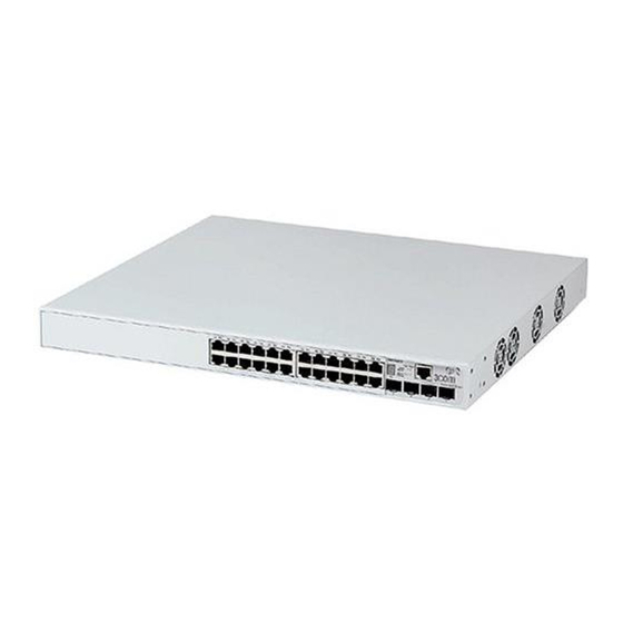
Physical Features This section describes the key features of the front and rear panel of the Switch 3870. Front Panel The front panel includes 24 or 48 10BASE-T/100BASE-TX/1000BASE-T network ports depending on the specific model you have purchased, 4 SFP ports that are shared with the last four RJ-45 ports (that is, port 21-24 on the 24-port Switch or port 45-48 on the 48-port Switch), an RJ-45 console port for management access, and various system status indicators. -
Page 14: Console Port
1: I 3870 HAPTER NTRODUCING THE WITCH connect RJ-45 data connectors, network telephony systems, or network telephones to these sockets. Either shielded or unshielded data cables with shielded or unshielded jacks can be connected to these data sockets. 10BASE-T/100BASE-TX/1000BASE-T Ports The 10BASE-T/100BASE-TX/1000BASE-T ports have RJ-45 connectors and are configured as Auto MDIX (cross-over). - Page 15 The console port on the Switch is set to autobaud (up to a maximum of 19,200 baud), 8 data bits, no parity, and 1 stop bit. LEDs Table 4 lists LEDs visible on the front of the Switch, and how to read their status according to color.
- Page 16 1: I HAPTER NTRODUCING THE Module LEDs Packet Status Unit LED Power/Self Test LED Fault LED 3870 WITCH Color Indicates Yellow Packets are being transmitted/received on the port. No packets are being transmitted/received on the port. Green The module is installed and supported and the link status has been determined.
-
Page 17: Rear Panel
Rear Panel The rear panel includes a standard AC power socket and a redundant power socket, a slot for an optional expansion module, and two stacking ports. Figure 3 Rear View of the Switch 3870 Power Socket Redundant Power System Socket Expansion Module Slot You can use this slot to install a 10-Gigabit Ethernet expansion module. -
Page 18: Default Settings
1: I HAPTER NTRODUCING THE Some combinations of stacked 24-port and 48-port units restrict the number of modules supported by the stack. Table 5 shows which stack configurations restrict the number of supported modules. Table 5 Maximum Stack Configurations Default Settings Table 6 shows the default settings for the Switch 3870. - Page 19 If you initialize a Switch unit by selecting System > Control > Initialize on the Web interface or by entering system control initialize on the command line interface, the following settings are retained to allow you to connect to and manage the Switch: IP address ■...
- Page 20 1: I 3870 HAPTER NTRODUCING THE WITCH...
-
Page 21: Installing The Switch
NSTALLING THE This chapter contains the information you need to install and set up the Switch 3870. It covers the following topics: Package Contents ■ Choosing a Suitable Site ■ Rack-Mounting the Switch ■ Placing Units On Top of Each Other ■... -
Page 22: Package Contents
■ ■ ■ ■ ■ If any of the above items are damaged or missing, contact your 3Com network supplier immediately. Choosing a Suitable The Switch 3870 is suited for use in an internal wiring closet, a network Site room, or telecommunications room, where it can be mounted in a standard 19-inch equipment rack, or free-standing. -
Page 23: Rack-Mounting The Switch
Water or moisture cannot enter the case of the Switch. Airflow is not restricted around the Switch or through the vents in the side of the Switch. 3Com recommends that you provide a minimum of 25 mm (1 in.) clearance. -
Page 24: Montagesatz Anweisungen
2: I HAPTER NSTALLING THE To rack-mount your Switch: 1 Place the Switch the right way up on a hard, flat surface with the front facing towards you. 2 Locate a mounting bracket over the mounting holes on one side of the unit, as shown in Figure 4. -
Page 25: Placing Units On Top Of Each Other
Switch your network. Ensure that the power input to your system is clean and free from sags and surges to avoid unforeseen network outages. 3Com recommends that you install power conditioning, especially in areas prone to black outs, power dips and electrical storms. -
Page 26: Checking For Correct Operation Of Leds
2: I HAPTER NSTALLING THE The Switch is intended to be grounded. Ensure it is connected to earth ground during normal use. Installing proper grounding helps avoid damage from lightning and power surges. Before powering on the Switch, verify that the network cables and the power cable are securely connected. -
Page 27: Choosing The Correct Cables
MDI port, you need to use a standard straight-through cable. See Table 8. 3Com recommends that you use, at least, Category 5 twisted pair cable. The maximum segment length for this type of cable is 100 m (328 ft.). -
Page 28: Using Sfp Transceivers
■ ■ To access the latest list of approved SFP transceivers for the Switch on the 3Com Web site, enter this URL into your internet browser: www.3com.com Inserting an SFP To be recognized as valid, the SFP transceiver must have the following... - Page 29 If the SFP transceiver is faulty, it will not operate within the Switch. See “Solving Hardware Problems” on page 51. 3Com recommends that you only use SFP transceivers supplied by 3Com. If the SFP transceiver is invalid, it will not be recognized by the Switch.
-
Page 30: Removing An Sfp Transceiver
2: I HAPTER NSTALLING THE Figure 5 Inserting an SFP Transceiver 4 Use an appropriate cable to connect the transceiver to a suitable device. 5 Check the LEDs on the front of the Switch to ensure that it is operating correctly. -
Page 31: Setting U P For Management
ETTING Your Switch can operate in its default state, that is, you can install it and it will work straight away (plug-and-play). However, to make full use of the features offered by the Switch, and to change and monitor the way it works, you have to access the management software that resides on the Switch. -
Page 32: Overview Of Management Setup
See page 41 Power on the Switch. See page 31 Do you want to manually How do you want to view the automatically configured IP information? Use 3Com Network Connect to the console Supervisor (3NS). See page 36 SNMP Web Interface... -
Page 33: Automatic Ip Configuration
(Static IP addresses are necessary to ensure that the Switch is always allocated the same IP information.) For most installations, 3Com recommends that you configure the Switch IP information manually. This makes management simpler and more reliable as it is not dependent on a DHCP server, and eliminates the risk of the IP address changing. -
Page 34: Preparing For Management
For detailed information about the specific Web interface operations and command line interface commands and problem solving, refer to the “Management Interface Reference Guide” on the CD-ROM that is supplied with the Switch or on the 3Com Web site. ANAGEMENT Your network uses DHCP to allocate IP information, or Flexibility is needed. -
Page 35: Manually Configuring Ip Information
Manually You can manually configure the Switch IP information by connecting a Configuring IP workstation using a console cable to the console port of the Switch. You Information can then manually enter IP information using the command line interface (CLI). Connecting to the To set up your Switch manually, you can alternatively make a connection Console Port... -
Page 36: Connecting The Workstation To The Switch
3: S HAPTER ETTING P FOR Connecting the Workstation to the Switch 1 Connect the workstation to the console port using an RJ-45 to DB9 converter cable and a standard null modem cable, as shown in Figure 7. Figure 7 Connecting a Workstation to the Switch Via the Console Port To connect the cable: a Insert the RJ-45 end of the RJ-45 to DB9 converter cable into the b Connect the null modem cable to the DB9 end of the converter cable. - Page 37 Return at the password prompt. If you have logged on correctly, the top-level menu of the command line interface is displayed as shown in the example in Figure 8. Figure 8 Example Top-level Command Line Interface Menu Menu options: -------3Com SuperStack 3 Switch 3870 48-port-------- bridge - Administer bridge-wide parameters feature...
-
Page 38: Viewing Automatically Configured Ip Information
IP address the Switch will be given. Refer to the documentation that accompanies your DHCP server. If your network does not have a DHCP server, the workstation running 3Com Network Supervisor must be on the same subnet as the Switch, because Auto-IP addresses are non-routable. Connecting to the... - Page 39 Viewing Automatically Configured IP Information Prerequisites A workstation with terminal emulation software installed, such as ■ Microsoft HyperTerminal. This software allows you to communicate with the Switch via the console port directly. Documentation supplied with the terminal emulation software. ■ A suitable cable: ■...
- Page 40 Return at the password prompt. If you have logged on correctly, the top-level menu of the command line interface is displayed, as shown in the example in Figure 10. Figure 10 Example Top-level Command Line Interface Menu Menu options: -------3Com SuperStack 3 Switch 3870 48-port-------- bridge feature gettingStarted...
-
Page 41: Methods Of Managing A Switch
The initial setup of your Switch is now complete and you can now set up your chosen management method. See “Methods of Managing a Switch” on page 39. If you do not intend to use the command line interface via the console port to manage the Switch, you can disconnect the serial cable and close the terminal emulator software. -
Page 42: Web Interface Management
You can manage a Switch using any network management workstation running the Simple Network Management Protocol (SNMP), as shown in Figure 14. For example, you can use the 3Com Network Supervisor application, which is available for download from the 3Com Web site. -
Page 43: Cli Management Over The Network
Your Switch is now ready to continue being managed and/or configured through the CLI via its console port. CLI Management over To manage the Switch using the command line interface over a network the Network using Telnet: 1 Ensure you have already set up the Switch with IP information as described in “Overview of Management Setup”... -
Page 44: Setting Up Web Interface Management
3: S HAPTER ETTING P FOR Setting Up Web This section describes how you can set up Web interface management Interface over the network. Management Prerequisites ■ ■ ■ Choosing a Browser To display the Web interface correctly, JavaScript and Cascading Style Sheets must be enabled on your browser. -
Page 45: Setting Up Snmp Management
■ You can use the 3Com Network Supervisor application, which is available for download from the 3Com Web site. You can also use the 3Com Network Director (Version 2.0) to manage your Switch via SNMP. This optional network management application can be purchased directly from the 3Com Web site. -
Page 46: Default Users And Passwords
3: S HAPTER ETTING P FOR Default Users and If you intend to manage the Switch using the Web interface or the Passwords command line interface, or to change the default passwords, you need to log on with a valid user name and password. The Switch has three default user names, and each user name has a different password and level of access. -
Page 47: Backing Up And Restoring Over The Web Interface
Switch is attached. If you are not sure that the configuration settings will work properly in the current network environment, 3Com advises you to disconnect the Switch from the network and connect it directly to the management station before attempting to restore the configuration settings. -
Page 48: Backing Up And Restoring Over The Cli
1 (Optional Step) If you are restoring configuration settings in an attempt to resolve system configuration errors, 3Com recommends that you first reset the Switch to its factory defaults. To do this, select System -> Control -> Initialize in the Navigation Tree, and click OK. -
Page 49: Backing Up And Restoring With Snmp
CLI or Web interface as described in the preceding sections. The 3Com Network Director (version 2.0) can be used to back up and restore device configuration settings directly through the application’s SNMP interface. - Page 50 ASCII format used by the Switch itself, locate the *.stack backup file specified at the end of this display, stored in the Program Files\3Com\Network Director\backups directory, and open it with any standard text editing tool.
-
Page 51: Problem Solving
ROBLEM This chapter helps you to diagnose and solve problems you may have with the operation of your Switch. There is also an explanation of IP addressing. The topics covered are: Solving Problems Indicated by LEDs ■ Solving Hardware Problems ■... -
Page 52: Solving Problems Indicated By Leds
■ ■ If this does not solve the problem, contact your 3Com network supplier for assistance. The Unit LED will not light if the Switch 3870 is a standalone unit. If the Switch 3870 is part of a stack, the Unit ID will be shown. -
Page 53: Solving Hardware Problems
■ ■ When you power on the Switch, the Power/Self Test LED lights yellow for about 10 seconds, after which it starts flashing green. This is normal and does not indicate any of the above conditions. A Port Status LED is flashing green/yellow The port has failed and has been automatically disabled. - Page 54 4: P HAPTER ROBLEM OLVING A fan failure warning message is received Your Switch has a fan monitoring system that will generate fan failure warning messages. Fan failure could potentially reduce the lifetime of the Switch. The monitoring system polls the fan status at periodic intervals while the unit is powered on.
-
Page 55: Solving Communication Problems
The Switch has identified that the SFP does not meet the minimum requirements for the Switch and has disabled the port. To correct this problem, completely remove the SFP and replace it with a 3Com approved SFP. See “Approved SFP Transceivers” on page 26. - Page 56 If your IP network is internal to your organization only, that is, you do not access the Internet, you may use any arbitrary IP address as long as it is not being used by another device on your network. 3Com suggests you use addresses in the range 192.168.0.0 to 192.168.255.255 with a subnet mask of 255.255.255.0.
-
Page 57: Solving Software Upgrade Problems
Solving Software You can upgrade the management software of the Switch by using the Upgrade Problems System > Control > Software Upgrade operation on the Web interface, or the system control softwareUpgrade command on the command line interface. For details on these options, refer to the Management Interface Reference Guide supplied in HTML format on the CD-ROM that accompanies your Switch. - Page 58 4: P HAPTER ROBLEM OLVING...
-
Page 59: Safety Information
AFETY NFORMATION You must read the following safety information before carrying out any installation or removal of components, or any maintenance procedures on the Switch 3870. WARNING: Warnings contain directions that you must follow for your personal safety. Follow all directions carefully. You must read the following safety information carefully before you install or remove the unit. -
Page 60: Power Cord Set - Japan
A: S PPENDIX AFETY NFORMATION przestrzegać wszystkich wskazówek. Przed instalacją lub demontażem urządzenia należy uważnie przeczytać poniższe informacje o bezpieczeństwie. Power Cord Set Japan — Important Safety Information WARNING: Installation and removal of the unit must be carried out by qualified personnel only. - Page 61 Europe only: The supply plug must comply with CEE 7/7 (“SCHUKO”). ■ The mains cord must be <HAR> or <BASEC> marked and ■ be of type H03VVF3GO.75 (minimum). Denmark The supply plug must comply with section 107-2-D1, ■ standard DK2-1a or DK2-5a. Switzerland The supply plug must comply with SEV/ASE 1011.
-
Page 62: L'information De Sécurité Importante
A: S PPENDIX AFETY NFORMATION tool. Keep the blanking plate and the fixings in a safe place. If you remove the Module at any time, you must then replace the blanking plate. WARNING: Fiber optic ports - optical safety Class 1 LASER PRODUCT Never look at the transmit laser while it is powered on. - Page 63 AVERTISSEMENT: Cordon électrique: Il doit être agréé ans le pays d'utilisation: Etats-Unis et Le cordon doit avoir reçu l'homologation des UL et un ■ Canada certificat de la CSA Le cordon souple doit respecter, à titre minimum, les ■ spécifications suivantes : calibre 18 AWG type SV ou SJ à...
- Page 64 A: S PPENDIX AFETY NFORMATION connexion portant l'appellation Neutre et avec raccordement direct à la terre (masse). AVERTISSEMENT: Points d’accès RJ-45. Ceux-ci sont protégés par des prises de données. Ils ne peuvent pas être utilisés comme prises de téléphone conventionnelles standard, ni pour la connection de l’unité à un réseau téléphonique central privé...
-
Page 65: Wichtige Sicherheitsinformationen
Wichtige Sicherheitsinformationen VORSICHT: Die Installation und der Ausbau des Geräts darf nur durch Fachpersonal erfolgen. VORSICHT: Wenn Sie einen Switch 3870 zusammen mit schmaleren SuperStack Einheit unterhalb dieser schmaleren Einheiten aufgestellt werden. VORSICHT: Das Gerät muß geerdet sein. VORSICHT: Das Gerät muß an eine geerdete Steckdose angeschlossen werden, die europäischen Sicherheitsnormen erfüllt. -
Page 66: Información De Seguridad Importante
A: S PPENDIX AFETY NFORMATION Erdung angeschlossen sein. † Impédance à la terre. VORSICHT: RJ-45-Porte. Diese Porte sind geschützte Datensteckdosen. Sie dürfen weder wie normale traditionelle Telefonsteckdosen noch für die Verbindung der Einheit mit einem traditionellem privatem oder öffentlichem Telefonnetzwerk gebraucht werden. Nur RJ-45-Datenanscluße, Telefonnetzsysteme or Netztelefone an diese Steckdosen anschließen. - Page 67 unidad Switch 3870 debe instalarse debajo de las unidades más estrechas. ADVERTENCIA: La unidad debe tener toma de tierra (conexión a tierra). ADVERTENCIA: Conecte la unidad a una fuente de alimentación con toma de tierra para garantizar el cumplimiento de las normas de seguridad.
- Page 68 A: S PPENDIX AFETY NFORMATION ADVERTENCIA: El enchufe debe estar cerca de la unidad y ser de fácil acceso. La única forma de cortar la alimentación de la unidad consiste en desconectar el cable eléctrico de la toma de corriente. ADVERTENCIA: Esta unidad funciona en condiciones SELV (voltaje extrabajo de seguridad) de conformidad con la norma IEC 60950.
-
Page 69: Importanti Informazioni Di Sicurezza
ADVERTENCIA: Puertos de fibra óptica: seguridad óptica No mire nunca al láser de transmisión mientras esté encendido. No mire nunca directamente al puerto de transmisión de fibra óptica ni a los extremos del cable de fibra óptica mientras estén conectados. El uso de controles, ajustes de rendimiento o procedimientos distintos a los especificados en este documento puede producir emisiones de láser peligrosas. - Page 70 A: S PPENDIX AFETY NFORMATION AVVERTENZA: L'accoppiatore (il connettore all'unità e non la spina a muro) deve avere una configurazione abbinabile a una presa EN60320/IEC320. AVVERTENZA: La presa deve trovarsi vicino all'unità ed essere facilmente accessibile. L'unico modo per rimuovere l'alimentazione dall'unità consiste nello scollegare il cavo di alimentazione dalla presa.
-
Page 71: Ważne Informacje O Zabezpieczeniach
Wa¿ne Informacje o Zabezpieczeniach privato) o a una rete telefonica pubblica. Collegare a queste porte solo prese dati RJ-45, sistemi di telefonia o telefoni di rete. A queste prese dati è possibile collegare cavi dati schermati o non schermati con prese dati schermate o non schermate. - Page 72 A: S PPENDIX AFETY NFORMATION Niezbędna jest zgodność z przepisami kraju, w którym jest stosowany: OSTRZEŻENIE: Złączka urządzenia (podłączona do przełącznika, a nie do wtyczki ściennej) musi być odpowiednio dopasowana do normy EN60320/IEC320 otworu wlotowego. OSTRZEŻENIE: Gniazdo zasilające musi być umieszczone w pobliżu urządzenia i musi być...
- Page 73 Wa¿ne Informacje o Zabezpieczeniach † impédance a la terre OSTRZEŻENIE: Tylko Wielka Brytania: Podczas podłączania modemu do portu konsoli Switch 3870 należy stosować tylko modem odpowiedni do podłączenia do sieci telekomuni- kacyjnej. OSTRZEŻENIE: Porty RJ-45. Są to ekranowane gniazda danych RJ-45. Nie mogą...
- Page 74 A: S PPENDIX AFETY NFORMATION...
-
Page 75: Null Modem Cable
Null Modem Cable RJ-45 to RS-232 25-pin Switch 3870 Cable connector: RJ-45 female PC-AT Serial Cable RJ-45 to 9-pin Switch 3870 Cable connector: RJ-45 female OUTS Screen Shell Ground Screen Shell Ground PC/Terminal Cable connector: 25-pin male/female Screen only required if screen always required Ground required for handshake... -
Page 76: Pin Assignments
B: P PPENDIX OUTS RJ-45 Pin Pin assignments are identical for 10/100 and 1000 RJ-45 connectors. Assignments Table 10 Pin Assignments Table 11 Pin Assignments Pin Number 10/100 Ports configured as MDI Transmit Data + Transmit Data - Receive Data + Not assigned Not assigned Receive Data –... -
Page 77: Technical Specifications
–10 ° to +70 °C (14 ° to 158 °F) 10–95% relative humidity, non-condensing EN60068 to 3Com schedule (package testing: paras 2.1, 2.2, 2.30 and 2.32. Operational testing: paras 2.1, 2.2, 2.30 and 2.13. UL 60950, EN60950, CSA 22.2 No. 60950, IEC 60950, IEC825-1, EN60825-1... -
Page 78: Switch 3870 (48 Port)
–10 ° to +70 °C (14 ° to 158 °F) 10–95% relative humidity, non-condensing EN60068 to 3Com schedule (package testing: paras 2.1, 2.2, 2.30 and 2.32. Operational testing: paras 2.1, 2.2, 2.30 and 2.13. UL 60950, EN60950, CSA 22.2 No. 60950, IEC 60950, IEC825-1, EN60825-1... -
Page 79: Upport For Your
3Com Extended Warranty and Professional Services is available at http://www.3com.com/ Contact your authorized 3Com reseller or 3Com for additional product and support information. Troubleshoot You will find support tools posted on the 3Com Web site at Online www.3com.com/ ■ BTAINING... -
Page 80: Access Software Downloads
Downloads of software initially purchased with the product. In order to access these Software Updates you must first register your product on the 3Com Web site at First time users will need to apply for a user name and password. A link to... - Page 81 To send a product directly to 3Com for repair, you must first obtain a return authorization number (RMA). Products sent to 3Com, without authorization numbers clearly marked on the outside of the package, will be returned to the sender unopened, at the sender’s expense. If your...
- Page 82 Latin America Telephone Technical Support and Repair Antigua Barbuda AT&T +800 988 2112 Argentina Local Number 54 11 5556 3200 Argentina 0 810 444 3COM Argentina 810 44 32 66 Aruba AT&T +800 998 2112 Bahamas AT&T +800 998 2112 Barbados AT&T +800 998 2112...
-
Page 83: Index
NDEX access levels of default users 44 automatic setup 36 3Com Network Supervisor 36 console port 36 cable 15 10/100/1000 25 pin-outs 73 CD-ROM 7 command line interface management 39 setting up 40 using console port 40 using Telnet 41... - Page 84 NDEX pin assignments null modem cable 73 RJ45 74 serial cable 73 pin-outs 73 ports 10/100/100 12 SFP 12 power socket 15 powering on a Switch 3870 23 problem solving 49 communication problems 53 fan failure 52 hardware problems 51 IP addressing 53 LEDs 50 thermal shutdown 52...
- Page 85 Warning: This is a class A product. In a domestic environment this product may cause radio interference in which case the user may be required to take adequate measures. You must only insert a 3Com approved SFP transceiver into the Switch. These are listed in the “Approved SFP Transceivers” on page 26.
Need help?
Do you have a question about the SuperStack 3 3870 and is the answer not in the manual?
Questions and answers