Table of Contents
Advertisement
Advertisement
Table of Contents

Subscribe to Our Youtube Channel
Related Manuals for oConnor 1040


Summary of Contents for oConnor 1040
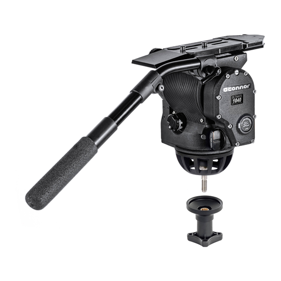
- Page 1 User Guide Oconnor 1040 Fluid Pan & Tilt Head Part No. C1265-0001 www.ocon.com...
- Page 2 Vitec Production Solutions reserves the right to make changes to product design and functionality without notification. Trademarks OConnor® is a registered trademark of the Vitec Group Plc. All product trademarks and registered trademarks are the property of The Vitec Group Plc.
-
Page 3: Table Of Contents
Contents Safety / About This Guide ....3 Operation ........17 Health and Safety ........3 Operating the Pan and Tilt Locks .. -
Page 4: Safety / About This Guide
Safety / About This Guide Important information on the safe installation and operation of this WARNING! Toppling hazard. Do not leave unattended. product. Read this information before operating the product. For your Keep out of reach of children. personal safety, read these instructions. Do not operate the product if you do not understand how to use it safely. -
Page 5: About This Guide
This guide describes the installation, configuration and operation of the OConnor Ultimate 1040 Fluid Head. The Ultimate 1040 fluid head brings the same quality build and precision movement found the larger OConnor 2575 and 2065 heads to enable cinematographers easily move from heavier to lighter payload camera set-ups without compromise. -
Page 6: Box Contents
Box Contents 1040 Head C1265-0001 Large Euro Quick Release + Plate 1030-268 100 mm Ball Base 08365 100 mm Tie down S2052-1100 Pan handle 1030-246 Pan handle extension 2575-135... -
Page 7: Optional Accessories
Optional Accessories Assistants box CSE-MFB100 Front box mount 08308 Eye piece leveller C1504-1000 Platform Assemblies & Plates Large Euro quick release (includes large Euro C1030-268 Plate Part No. 08285) Camera Slide Plate assy. (Includes Mini Euro V4045-1901 Plate Part No. 08427) Tripods + Hi Hats 100mm Hi Hat 45A-0002... -
Page 8: Components
Components Front View Position Description Camera mounting plate Handle / accessory mounting rosette Clamp knob Platform release lever Pan lock lever Front box mounts Tie down (100 mm) Ball base (100 mm) Tilt drag indicator wheel Platform scale... -
Page 9: Rear View
Components Rear View Position Description Handle clamp Pan handle Tilt drag adjustment knob Counterbalance crank handle Provision for attachments Pan drag indicator wheel Battery compartment Pan drag adjustment knob Bubble level Tilt lock lever Bubble illumination button... -
Page 10: Installation
Installation Leveling the Head Mounting the Head The 1040 is installed onto standard tripods using the 100mm ball After securely mounting the head on to the tripod, center the bubble base and tie down level to set the level. Other bases are available See optional accessories). -
Page 11: Remove / Install Camera Plate Platform
Installation Remove / Install Camera Plate Platform The camera plate can be installed facing front or rear depending on the required load and balance requirements. Remove the camera plate as described on “Mounting the camera” on page 13. Release the plate slide lock (A) by levering in a clockwise direction. - Page 12 Installation Rotate the camera plate 180° and slide it on to the head from the rear. Locate the Hex stop screw in the front facing thread and tighten, this will prevent the plate from sliding off the head.
-
Page 13: Fitting The Pan Handle
Installation Fitting the Pan Handle Pan Handle accessory mounting rosettes are located at the rear of the head, on both left and right sides. The pan handle may be positioned on the rosettes in any position to suit the user requirements. -
Page 14: Mounting The Camera
The chart below shows the range of load and C of G heights that can be maintained in balance. The area below the balance curve (to the left) corresponds to load / C of G combinations that can be balanced over the full tilt range of the 1040. The area above the balance curve (to the right) corresponds to load / C of G combinations that exceed the capacity of the head. - Page 15 Installation If you are installing the head on a crane, pedestal, or dolly, you must Securely attach the camera plate to the bottom of the camera (D). lock them before installing the camera. Insert the camera plate into the platform. Push it into the dovetail at the rear of the platform, with the clamp in position (E), then To Mount the Camera: push the front down until the platform hook engages with an...
-
Page 16: Balancing The Payload
Installation Balancing the Payload Caution! The camera, handles and all accessories must be fitted in their operational position before balancing the The purpose of setting the balance and counterbalance of the head. Any equipment fitted or adjusted later can unbalance payload is to negate the weight of the payload when tilting the head. - Page 17 Installation The payload C of G (Centre of Gravity) must align with the fluid • If the camera springs back toward horizontal then the head’s tilt axis as shown below, slide the payload fore and aft counter balance requires lowering, turn the counterbalance using the camera plates sliding platform until the load is centered counterclockwise.
-
Page 18: Operation
Operation Operating the Pan and Tilt Locks The pan and tilt friction locks are operated by the levers on the left side of the head. Tilt After prolonged use, if the lock does not fully engage at the end of the lock travel, refer to “Adjust Lock Levers” on page 20. The levers are designed so they can be released simultaneously with one hand. -
Page 19: Pan And Tilt Fluid Drag
Operation Pan and Tilt Fluid Drag The pan drag adjustment knob is located on the lower right rear of the head, and the tilt drag adjustment knob on the lower left of the head. Both controls are continuously adjustable from 1 to 5. To increase drag, turn the knob clockwise, to decrease the drag, turn the knob counter-clockwise. -
Page 20: Maintenance
Maintenance Battery Replacement The battery illuminates the bubble level. It should be replaced whenever the illumination is inadequate. Use a coin or flat screwdriver to unscrew the battery cover. Carefully pull the battery out of it’s compartment. Fit a replacement CR 2032 3V battery in the compartment, ensuring that the positive side (+) of the battery faces outermost. Replace the battery cover and tighten using a coin or flat blade screwdriver. -
Page 21: Adjust Lock Levers
Maintenance Adjust Lock Levers Pull the lever off the hexagonal shaft, rotate it approximately 30° away from the “locked” end of the travel, and reinstall it. If the pan and / or tilt friction locks do not fully engage at the end of the lock lever travel, adjust the lever position as follows: Tighten the screw. -
Page 22: Adjust Camera Plate
Maintenance Adjust Camera Plate If movement is detected in the camera plate or the lock lever is to stiff, Using a hex key, adjust the small grub screw (clockwise to tighten the clamp must be adjusted. Release the clamp lever (turn clockwise) the clamp and counterclockwise to loosen the clamp). -
Page 23: Technical Specifications
Technical Specifications Height Width 8 in. (20.3 cm) 11.3” (28.7 cm) Depth Weight 7.5 in (19.1 cm) 16.2 lb (4.8 kg) with large Euro plate + Tie down *Maximum payload Weight 45 lb (20 kg) 0.88 lb (0.4 kg) Pan Bar Storage temp. - Page 24 Publication No. C1265-4980/0 www.ocon.com...
Need help?
Do you have a question about the 1040 and is the answer not in the manual?
Questions and answers