Table of Contents
Advertisement
Quick Links
C H A P T E R O V E R V I E W
Operating Instructions
ECC - Electronic Compressor Control (if equipped)
Spare Parts Lists
..........................................................................................................................
Options (if equipped)
Attachment
....................................................................................................................................
Manufacturer in terms of 97/23/EC
The full name and address of the manufacturer is:
Lenhardt & Wagner GmbH
An der Tuchbleiche 39
68623 Hüttenfeld / Germany
Phone: +49 (0) 62 56 - 85 88 0 - 0
Fax: +49 (0) 62 56 - 85 88 0 - 14
E-Mail: service@lw-compressors.com
Internet: www.lw-compressors.com
..............................................................................................................
.................................................................................................................
.........................................................
A
B
C
D
E
Advertisement
Chapters
Table of Contents

Related Manuals for L&W Compressors LW 200 B MC


Summary of Contents for L&W Compressors LW 200 B MC
- Page 1 C H A P T E R O V E R V I E W ......................Operating Instructions ............ECC - Electronic Compressor Control (if equipped) Spare Parts Lists .......................... Options (if equipped) ......................... Attachment ............................ Manufacturer in terms of 97/23/EC The full name and address of the manufacturer is: Lenhardt &...
- Page 2 S E R V I C E I N F O R M A T I O N / W A R R A N T Y Compressor information Type designation Serial number Date of construction Purchase information Purchase date First commissioned on Warranty period Dealer's stamp...
- Page 3 Operating Instructions Breathing Air Compressor LW 200 B MC / LW 250 B MC Version: 01.05.2020...
-
Page 4: Table Of Contents
First Commissioning ........................ 23 - 24 Daily Commissioning ........................25 Filling Procedure ..........................26 Switch off the Compressor ......................27 Remedying Faults ......................29 - 32 LW 200 B MC / 250 B MC Page A - 2 Version: 01.05.2020... - Page 5 Maintenance Records ......................60 - 64 Storage Conservation / Storage of the Compressor ..................65 De-conservation, Commissioning ....................66 Transportation Instructions / Disposal / Electric and Electronic Components ........67 LW 200 B MC / 250 B MC Page A - 3 Version: 01.05.2020...
-
Page 6: General Information / Description Of Marks And Warning Signs
Indicates a potentially hazardous situation which, if not avoided, could result in physical injury or damage to the product or environment. Note Indicates additional information on how to use the unit. LW 200 B MC / 250 B MC Page A - 4 Version: 01.05.2020... -
Page 7: Scope Of Delivery
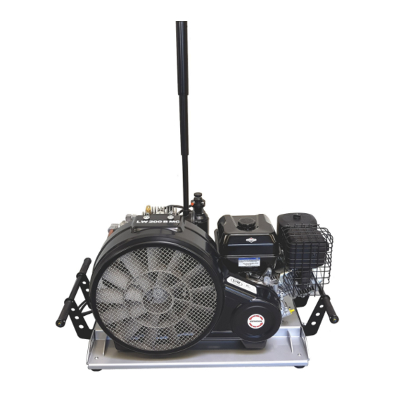
D E S C R I P T I O N Scope of Delivery LW 200 B MC / 250 B MC The MC Serie is the perfect solution for dive centers, ships, boats and places with limited space and convince with a brand new and powerful compressor block. -
Page 8: Technical Data
Dimensions with telescope intake pipe 1060 x 500 x 1300 1060 x 500 x 1300 B x T x H [mm]: Weight [kg]: Content Volume Filter housing [l]: 0.44 0.44 LW 200 B MC / 250 B MC Page A - 6 Version: 01.05.2020... -
Page 9: Unit Assembly
Designation Drive Engine Final Filter Housing with Safety Valve Condensate Drain Hoses Filling Hose with Filling Valve and Filling Pressure Gauge Compressor Block Telescope Intake Pipe LW 200 B MC / 250 B MC Page A - 7 Version: 01.05.2020... -
Page 10: Drive Engine
D E S C R I P T I O N Drive Engine Designation Throttle Control Choke Fuel Shut-off Starter Cord handle Stop Switch LW 200 B MC / 250 B MC Page A - 8 Version: 01.05.2020... -
Page 11: Flow Chart
10. Condensate Release Hose 22. Pressure Gauge (Filling Pressure) 11. 3rd Pressure Stage 23. Vent Valve 12. Cooling Pipe Final Stage 24. Unit Filling Valve "Cross Design" LW 200 B MC / 250 B MC Page A - 9 Version: 01.05.2020... -
Page 12: Safety Precautions
S A F E T Y P R E C A U T I O N S... -
Page 13: Intended Use / Operators
Only trained personnel are permitted to work on the unit! Warning Work on the electrical equipment on / with the machine / unit may only be carried out by qualified electricians. LW 200 B MC / 250 B MC Page A - 11 Version: 01.05.2020... -
Page 14: Safety Instructions On The Unit
Importance of notes and warning signs that are affixed to the compressor according to the applica- tion or its equipment. Warning Note High voltage! Ensure correct direction of rotation! Warning surfaces! LW 200 B MC / 250 B MC Page A - 12 Version: 01.05.2020... -
Page 15: General Safety Precautions
• Do not use the product in areas prone to explosion or in the presence of flammable gases. The product is not designed for these applications. An explosion might be the result if certain conditi- ons apply. LW 200 B MC / 250 B MC Page A - 13 Version: 01.05.2020... -
Page 16: Unit Customised Safety Notices
• Soundproofing equipment on the compressor has to be activated in safety function during ope- ration. • When handling with fats, oils and other chemical agents, observe the note for the product- related safety. LW 200 B MC / 250 B MC Page A - 14 Version: 01.05.2020... -
Page 17: Maintenance Instructions
• Only personnel with particular knowledge and experience with pneumatics may carry out work on pneumatic equipment. • Only personnel with particular knowledge and experience in gas equipment may carry out work on gas equipment. LW 200 B MC / 250 B MC Page A - 15 Version: 01.05.2020... -
Page 18: Transportation Instructions / Safety Regulations
No guarantees whatsoever are valid for damage caused or favoured by the non-consideration of these directions for use. LW 200 B MC / 250 B MC Page A - 16... -
Page 19: Installation
I N S T A L L A T I O N... -
Page 20: Outdoor Installation
Position compressor in direction of wind so that exhaust fumes are blown away from the unit. • Intake air must be free from noxious gas e.g. smoke, solvent vapours, exhaust fumes etc. • Observe the specified operating temperature (see "Technical Data")! LW 200 B MC / 250 B MC Page A - 18 Version: 01.05.2020... -
Page 21: Dimensions
I N S T A L L A T I O N Dimensions Fig. Dimensions LW 200 B MC / 250 B MC Page A - 19 Version: 01.05.2020... -
Page 22: Minimum Distances
Front side min. 1500 mm, sides min. 500 mm, rear side min. 500 mm. Avoid anything in this area which can restrict the cooling air flow. 1500 Fig. Minimum distances LW 200 B MC / 250 B MC Page A - 20 Version: 01.05.2020... -
Page 23: Operation
O P E R A T I O N... -
Page 24: Important Operation Instructions
Ensure that all persons handling the compressor are familiar with function and operation of the unit. Wear hearing protection When working on a running machine, always wear hearing protection. LW 200 B MC / 250 B MC Page A - 22 Version: 01.05.2020... -
Page 25: First Commissioning
• Read carefully the handbook of the petrol engine. • Check if all filling valves are closed. Start the compressor - described on the following page. LW 200 B MC / 250 B MC Page A - 23 Version: 01.05.2020... - Page 26 - Open the condensate valves - If it's working order, air escape through the hoses. 17. Open all condensate valves and the filling valves carefully to vent. LW 200 B MC / 250 B MC Page A - 24 Version: 01.05.2020...
-
Page 27: Daily Commissioning
• Check drive engine oil level. • Check compressor oil level. • Check if filter cartridge is in place / observe filter cartridge life! • Ensure toxic-free, pure intake air. LW 200 B MC / 250 B MC Page A - 25 Version: 01.05.2020... -
Page 28: Filling Procedure
Fill the compressed air cylinder to the desired pressure; close slowly the valve of the cylinder. Switch off the compressor. Close and vent the filling valve. 10. Disconnect compressed air cylinder from filling valve. 11. Open condensate drain valves manually. LW 200 B MC / 250 B MC Page A - 26 Version: 01.05.2020... -
Page 29: Switch Off The Compressor
During filling process, the system can be shut down at any time by switching the stop switch in off - (0) position. LW 200 B MC / 250 B MC Page A - 27 Version: 01.05.2020... -
Page 30: Remedying Faults
R E M E D Y I N G F A U L T S... - Page 31 See chapter "Final pressure can not be reached" See chapter "Final pressure can not be reached" See chapter "Final pressure can not be reached" See chapter "Final pressure can not be reached" LW 200 B MC / 250 B MC Page A - 29 Version: 01.05.2020...
- Page 32 Mole carbon filter cartridge saturated Replace Compressor oil unsuitable Use prescribed oil quality Filter cartridge unsuitable Use prescribed filter type Cylinder(s), piston(s) or piston ring(s) defective Replace LW 200 B MC / 250 B MC Page A - 30 Version: 01.05.2020...
- Page 33 Correct settings valve too high Fuse / circuit breaker has tripped Check fusing of the power supply / observe reg- Valid only for E models ulations LW 200 B MC / 250 B MC Page A - 31 Version: 01.05.2020...
- Page 34 Observe prescribed operating temperatures Oil leak at the compressor block Tighten corresponding mounting screws, if nec- essary replace corresponding paper sealing / o- ring / shaft seal LW 200 B MC / 250 B MC Page A - 32 Version: 01.05.2020...
-
Page 35: Maintenance And Service
M A I N T E N A N C E A N D S E R V I C E... -
Page 36: Service, Repair And Maintenance
Carry out maintenance or service work when the unit is switched off and protected against unexpected restart. Warning Risk of burns! Carry out maintenance or service work when the unit has cooled down. LW 200 B MC / 250 B MC Page A - 34 Version: 01.05.2020... - Page 37 Check opening pressure of final safety valve Clean coolers Clean all oil/water separators, if less than 500 operating hours Service intake filter (depends on condition - if less than 500 operating hours) LW 200 B MC / 250 B MC Page A - 35 Version: 01.05.2020...
- Page 38 Replace sintered metal filter of oil separator 002123 Replace o-ring of the water separator 001255 Replace o-ring of the final filter housing 001769 Oil change 000001 LW 200 B MC / 250 B MC Page A - 36 Version: 01.05.2020...
- Page 39 011105 Replace all Inlet- / Outlet valves incl. Gaskets 1st stage 003652 2nd stage 000551 3rd stage 011123 Upper gasket 1st 003651 Lower gasket 1st 011103 LW 200 B MC / 250 B MC Page A - 37 Version: 01.05.2020...
-
Page 40: Service Kits
Fig. Service Kits Service Kits Compressor Operating Hours Order No. LW 200 B MC / LW 250 B MC 1000 h 011169 LW 200 B MC / LW 250 B MC 2000 h 011170 LW 200 B MC / 250 B MC Page A - 38 Version: 01.05.2020... -
Page 41: Check V-Belt Tension / Tension V-Belt / Settings
M A I N T E N A N C E A N D S E R V I C E Check V-Belt Tension The LW 200 B MC / 250 B MC compressors are driven by V-belts. Check correct V-belt tension regu- larly, adjust if necessary. The V-belt could lose tension during transportation. Please check the V-belt tension before starting the compressor. -
Page 42: Compressor Lubrication / Check Oil Level
Refill new compressor oil at least when the oil level reached the middle of the indicated area. Fig. Oil Sight Glass Caution First oil change after 25 operating hours. LW 200 B MC / 250 B MC Page A - 40 Version: 01.05.2020... -
Page 43: Oil Change
Approx. 800 ml synthetic compressor oil is necessary for one oil change. Only use synthetic com- pressor oil which is recommended as suitable from L&W. (P/N: 000001) LW 200 B MC / 250 B MC Page A - 41 Version: 01.05.2020... -
Page 44: Manual Condensation Dump System
The oil / water separator has an integrated sinter filter which has to be replaced every 1000 operating hours. LW 200 B MC / 250 B MC Page A - 42 Version: 01.05.2020... -
Page 45: Maintenance - Oil / Water Separators 2Nd Stage
The oil / water separator maintenance is now completed. Fig. 1 Fig. 2 Loosen Pipe Connection Loosen Screw Connection Fig. 4 Fig. 3 Change Sinter Filter Change O-ring LW 200 B MC / 250 B MC Page A - 43 Version: 01.05.2020... -
Page 46: Filter Housing / Filter Cartridge
Filter cartridges should be changed at the following intervals, at +20°C or more often, depending on humidity and ambient temperature: • 31 hours for LW 200 B MC (Order No.: 011189) • 25 hours for LW 250 B MC (Order No.: 011189) Caution Do not run the compressor with empty unfilled cartridges. -
Page 47: Filter Cartridge Change
Fig. 5 Pull out the Filter Cartridge Filter Adapter Installed Filler Adapter Note Ensure that the old filter cartridge is disposed correctly at an approved waste point. LW 200 B MC / 250 B MC Page A - 45 Version: 01.05.2020... -
Page 48: Maintenance - Filter Housing
• Screw the filter housing cover in by using the filter key (Fig. 1). The filter housing maintenance is now completed. Fig. 1 Fig. 2 Change O-ring Remove / screw in Filter Housing Cover LW 200 B MC / 250 B MC Page A - 46 Version: 01.05.2020... -
Page 49: Inlet Filter
Maintenance intervals We recommend that the filter cartridge should be replaced every 500 working hours (depending on pollution grade). Fig. Inlet Filter LW 200 B MC / 250 B MC Page A - 47 Version: 01.05.2020... -
Page 50: Maintenance - Inlet Filter Housing
The filter inlet change is now completed. Fig. 1 Fig. 2 Fig. 3 Disconnect the Crankcase Breather Intake Filter Housing Remove Mounting Screw Hose Fig. 4 Intake Filter Housing O-rings LW 200 B MC / 250 B MC Page A - 48 Version: 01.05.2020... - Page 51 Available Special Tool Special tool are not necessary for dismounting Inlet- / Outlet valves but make work easier. Order number: 006847 Fig. 2 Special Tool LW 200 B MC / 250 B MC Page A - 49 Version: 01.05.2020...
-
Page 52: Replace Inlet- / Outlet Valve 1St Stage
Loosen Mounting Screws of Disconnect the Loosen Pipe Connection the Fan Guard Crankcase Breather Hose Fig. 4 Fig. 5 Loosen Valve Head Remove Valve Head Screws LW 200 B MC / 250 B MC Page A - 50 Version: 01.05.2020... - Page 53 Valve Head Gasket and Inlet / Outlet Valve Fig. 7 Fig. 8 Fig. 9 Valve Head with Inlet / Outlet Valve Tighten Valve Head Mount Fan Guard Screws LW 200 B MC / 250 B MC Page A - 51 Version: 01.05.2020...
- Page 54 Fig. 1 Fig. 2 Fig. 3 Loosen Mounting Screws of Loosen Pipe Loosen Valve Head the Fan Guard Connection Screws Fig. 4 Remove Inlet / Outlet Valve LW 200 B MC / 250 B MC Page A - 52 Version: 01.05.2020...
- Page 55 Inlet- / Outlet valves change 2nd stage / 3rd stage is now completed. Fig. 6 Fig. 5 Fig. 7 Tighten Valve Head Insert new Inlet- / Outlet Valve Mount Fan Guard Screws LW 200 B MC / 250 B MC Page A - 53 Version: 01.05.2020...
-
Page 56: Safety Valves
If a safety valve blows off, it indicates problems with either inlet or outlet valve of the following stage. Note Replace defective safety valves immediately! Fig. 1 Fig. 2 Fig. 3 Safety Valve 1st Stage Safety Valve 2nd Stage Safety Valve 3rd Stage LW 200 B MC / 250 B MC Page A - 54 Version: 01.05.2020... -
Page 57: Pressure Maintaining / Non Return Valve
/ condensate drain valves. After compressor stop, the indicated filling pressure remains constant, if the non return valve is working correctly. LW 200 B MC / 250 B MC Page A - 55 Version: 01.05.2020... -
Page 58: Adjust Pressure Maintaining Valve
(final pressure = 0 bar). When valve settings are not clear (e.g. after disassembly / repair), start the adjustment with a low basic setting (turn adjusting bolt 3 full turns in). LW 200 B MC / 250 B MC Page A - 56 Version: 01.05.2020... -
Page 59: O-Rings - Filling Valve And Filling Hose
• Change o-ring, previously grease new o-ring. • Connect filling hose to the filling valve and tighten. Fig. 1 O-ring at the Filling Valve Fig. 2 O-ring at the Filling Hose LW 200 B MC / 250 B MC Page A - 57 Version: 01.05.2020... -
Page 60: Test Of Pressure Equipment
Max. numbers of load cycles for operation with max. allowable pressure variation Final pressure [bar] Load cycles Operating hours [h] 43750 10930 4400 1100 Caution The filter container has to be replaced after 15 years! LW 200 B MC / 250 B MC Page A - 58 Version: 01.05.2020... -
Page 61: Maintenance Records
M A I N T E N A N C E R E C O R D S... - Page 62 By adding themselves to this list, the person that signs it confirms having been given a yearly introduction/instruction about the function and operation of the compressor unit.Furthermore, they have be informed about the relevant safety rules and regualtions (TRG, DGRL, BetrSichV, GSG, GSGV). LW 200 B MC / 250 B MC Page A - 60 Version: 01.05.2020...
- Page 63 M A I N T E N A N C E R E C O R D S Top up oil, oil change Date Operating hours Oil quantity [l] Name LW 200 B MC / 250 B MC Page A - 61 Version: 01.05.2020...
- Page 64 M A I N T E N A N C E R E C O R D S Cartridge change Date Operating hours Difference Name LW 200 B MC / 250 B MC Page A - 62 Version: 01.05.2020...
- Page 65 M A I N T E N A N C E R E C O R D S Maintenance work Description Date, signature LW 200 B MC / 250 B MC Page A - 63 Version: 01.05.2020...
- Page 66 M A I N T E N A N C E R E C O R D S Replaced Parts Designation Part number Date, signature LW 200 B MC / 250 B MC Page A - 64 Version: 01.05.2020...
-
Page 67: Conservation / Storage Of The Compressor
• If compressor unit should be stored for a period of more than one year, an oil change is strongly recommended before it’s been re-used. • Fuel driven units only: fill up fuel tank to top level to avoid corrosion. LW 200 B MC / 250 B MC Page A - 65 Version: 01.05.2020... -
Page 68: De-Conservation, Commissioning
• Check safety valve relief pressure of final stage and/or pressure switch setting. • Check all connections and pipe work for leaks. • Once all above steps are completed, compressor unit is now ready for use. LW 200 B MC / 250 B MC Page A - 66 Version: 01.05.2020... -
Page 69: Transportation Instructions / Disposal / Electric And Electronic Components
The device can be returned to L&W. Please do not hesitate to contact us if you have any further questions on this issue. LW 200 B MC / 250 B MC Page A - 67 Version: 01.05.2020... - Page 70 E R S A T Z T E I L L I S T E N / S PA R E PA R T S L I S T S D E TA I L A N S I C H T E N / D E TA I L E D V I E W S...
- Page 71 I n h a l t s v e r z e i c h n i s Gesamtansicht Kompressor - Overall View Compressor ............. 1 Grundgestell - Main Frame ......................2 Motor - Engine ..........................4 Lüfterabdeckung - Fan Guard ..................... 6 Rohrleitungssystem - Pipework ....................
- Page 72 D E T A I L A N S I C H T / D E T A I L E D V I E W Gesamtansicht Kompressor / Overall View Compressor Version: 01.05.2020 LW 200 - 250 B MC C - 1...
- Page 73 E R S A T Z T E I L L I S T E / S P A R E P A R T L I S T Baugruppe: Grundgestell / Assembly: Main Frame Best.-Nr. / Order No. Benennung Description 000498 U-Scheibe A6...
- Page 74 D E T A I L A N S I C H T / D E T A I L E D V I E W Baugruppe: Grundgestell / Assembly: Main Frame Version: 01.05.2020 LW 200 - 250 B MC C - 3...
- Page 75 E R S A T Z T E I L L I S T E / S P A R E P A R T L I S T Baugruppe: Motor / Assembly: Engine Best.-Nr. / Order No. Benennung Description 000111 Keilriemen SPA 1332 V-Belt...
- Page 76 D E T A I L A N S I C H T / D E T A I L E D V I E W Baugruppe: Motor / Assembly: Engine Version: 01.05.2020 LW 200 - 250 B MC C - 5...
- Page 77 Rubber Grommet Ø18x24x7mm 011527 Ventilatorschutz mit Wellengitter Fan Guard 011533 Aufkleber "LW 200 B MC" Sticker "LW 200 B MC", white 011534 Aufkleber "LW 250 B MC" Sticker "LW 250 B MC", white Version: 01.05.2020 LW 200 - 250 B MC...
- Page 78 E R S A T Z T E I L L I S T E / S P A R E P A R T L I S T Baugruppe: Lüfterabdeckung / Assembly: Fan Guard Version: 01.05.2020 LW 200 - 250 B MC C - 7...
- Page 79 E R S A T Z T E I L L I S T E / S P A R E P A R T L I S T Rohrleitungssystem / Pipework Best.-Nr. / Order No. Benennung Description 000102 Einschraubstutzen DIN Füllanschluss Holder DIN Filling connector G5/8 000498...
- Page 80 D E T A I L A N S I C H T / D E T A I L E D V I E W Rohrleitungssystem / Pipework Version: 01.05.2020 LW 200 - 250 B MC C - 9...
- Page 81 E R S A T Z T E I L L I S T E / S P A R E P A R T L I S T Baugruppe: Kreuzventil / Assembly: Cross Design Valve Best.-Nr. / Order No. Benennung Description 000213...
- Page 82 000665 004977 Andere verfügbare Füllanschlüsse (Other available filling connectors) Benennung (Description) Best.-Nr. (Order No.) CGA 346 - 200bar 008394 CGA 347 - 300bar 006842 INT / Yoke - 200/232 bar 002307 LW 200 - 250 B MC C - 11...
- Page 83 E R S A T Z T E I L L I S T E / S P A R E P A R T L I S T Baugruppe: Endfiltergehäuse / Assembly: Final Filter Tower Best.-Nr. / Order No. Benennung Description 000506...
- Page 84 E R S A T Z T E I L L I S T E / S P A R E P A R T L I S T Baugruppe: Endfiltergehäuse / Assembly: Final Filter Tower Best.-Nr. / Order No. Benennung Description 003077...
- Page 85 D E T A I L A N S I C H T / D E T A I L E D V I E W Baugruppe: Endfiltergehäuse (Volumen 0,37 Ltr.) Assembly: Final Filter Tower (Volume 0.37 ltr.) Version: 01.02.2020 LW 200 - 250 B MC C - 14...
- Page 86 D E T A I L A N S I C H T / D E T A I L E D V I E W Baugruppe: Endfiltergehäuse (Volumen 0,44 Ltr.) Assembly: Final Filter Tower (Volume 0.44 ltr.) Version: 01.02.2020 LW 200 - 250 B MC C - 15...
- Page 87 D E T A I L A N S I C H T / D E T A I L E D V I E W Gesamtansicht Verdichtereinheit / Overall View Compressor Assembly Version: 01.05.2020 LW 200 - 250 B MC C - 16...
- Page 88 E R S A T Z T E I L L I S T E / S P A R E P A R T L I S T Baugruppe: Kompressorblock / Assembly: Compressor Block Best.-Nr. / Order No. Benennung Description 000220 Sicherheitsventil G3/8, 8 bar...
- Page 89 E R S A T Z T E I L L I S T E / S P A R E P A R T L I S T Baugruppe: Kompressorblock / Assembly: Compressor Block Best.-Nr. / Order No. Benennung Description 010811 Zylinder 1.Stufe...
- Page 90 D E T A I L A N S I C H T / D E T A I L E D V I E W Baugruppe: Kompressorblock / Assembly: Compressor Block Version: 01.07.2020 LW 200 - 250 B MC C - 19...
- Page 91 E R S A T Z T E I L L I S T E / S P A R E P A R T L I S T Baugruppe: Ansaugfilter / Assembly: Intake Filter Best.-Nr. / Order No. Benennung Description 001707 Ansaugfiltergehäuse...
- Page 92 E R S A T Z T E I L L I S T E / S P A R E P A R T L I S T Baugruppe: Ansaugfilter / Assembly: Intake Filter Version: 01.05.2020 LW 200 - 250 B MC C - 21...
- Page 93 E R S A T Z T E I L L I S T E / S P A R E P A R T L I S T Baugruppe: Öl- Wasserabscheider / Assembly: Oil- Water Separator Best.-Nr. / Order No. Benennung Description 000811...
- Page 94 D E T A I L A N S I C H T / D E T A I L E D V I E W Baugruppe: Öl- Wasserabscheider / Assembly: Oil- Water Separator Version: 01.02.2020 LW 200 - 250 B MC C - 23...
- Page 95 E R S A T Z T E I L L I S T E / S P A R E P A R T L I S T Baugruppe: Kolben 1. Stufe / Assembly: Piston 1st Stage Best.-Nr. / Order No. Benennung Description 000047...
- Page 96 E R S A T Z T E I L L I S T E / S P A R E P A R T L I S T Baugruppe: Kompressionskolben 2. Stufe Assembly: Compression Piston 2nd Stage Best.-Nr. / Order No. Benennung Description 010816...
- Page 97 E R S A T Z T E I L L I S T E / S P A R E P A R T L I S T Baugruppe: Kompressionskolben 3. Stufe Assembly: Compression Piston 3rd Stage Best.-Nr. / Order No. Benennung Description 010817...
- Page 98 E R S A T Z T E I L L I S T E / S P A R E P A R T L I S T Baugruppe: Saug & Druckventil 2. Stufe / Assembly: In & Outlet Valve 2nd Stage Best.-Nr.
- Page 99 E R S A T Z T E I L L I S T E / S P A R E P A R T L I S T Baugruppe: Saug & Druckventil 3. Stufe / Assembly: In & Outlet Valve 3rd Stage Best.-Nr.
- Page 100 E R S A T Z T E I L L I S T E / S P A R E P A R T L I S T Baugruppe: Kurbeltrieb / Assembly: Crank Drive Best.-Nr. / Order No. Benennung Description 000839 Verschlussstopfen...
- Page 101 D E T A I L A N S I C H T / D E T A I L E D V I E W Baugruppe: Kurbeltrieb / Assembly: Crank Drive Version: 01.02.2020 LW 200 - 250 B MC C - 30...
- Page 102 E R S A T Z T E I L L I S T E / S P A R E P A R T L I S T Baugruppe: Lagerdeckel schwungradseitig Assembly: Bearing Cover Flywheel Side Best.-Nr. / Order No. Benennung Description 001361...
- Page 103 E R S A T Z T E I L L I S T E / S P A R E P A R T L I S T Baugruppe: Kühler / Assembly: Cooler Best.-Nr. / Order No. Benennung Description 000498 U-Scheibe A6 Washer...
- Page 104 D E T A I L A N S I C H T / D E T A I L E D V I E W Baugruppe: Kühler / Assembly: Cooler Version: 01.05.2020 LW 200 - 250 B MC C - 33...
- Page 105 E R S A T Z T E I L L I S T E / S P A R E P A R T L I S T Baugruppe: Lüfterrad / Assembly: Flywheel Assembly Best.-Nr. / Order No. Benennung Description 001043 Zylinderschraube M8x35...
- Page 106 O P T I O N S...
- Page 107 I n h a l t s v e r z e i c h n i s Additional Filling Hose ........................ 1 Auto Shut Down .......................... 4 Hour Counter..........................7 Oil Pump ............................9 Oil Pressure Gauge ........................13 Interstage Pressure Gauge ......................
-
Page 108: Additional Filling Hose
A D D I T I O N A L F I L L I N G H O S E LW 200 - 250 B MC D - 1... - Page 109 A D D I T I O N A L F I L L I N G H O S E The additional hose with filling valve allows to fill two bottles simultaneously. The hose with fil- ling valve is available in 200 and 300 bar version. Please refer to Chapter A for all information about the filling process.
- Page 110 A D D I T I O N A L F I L L I N G H O S E Detailed View Version: 01.05.2020 LW 200 - 250 B MC D - 3...
-
Page 111: Auto Shut Down
A U T O S H U T D O W N LW 200 - 250 B MC D - 4... - Page 112 A U T O S H U T D O W N Final pressure switch The pressure switch shuts off the compressor automatically when the selected final pressure is reached. The final pres- sure switch is already adjusted to the corresponding cut-out pressure.
- Page 113 A U T O S H U T D O W N Spare Part List Best.-Nr. / Order No. Benennung Description 000203 Druckschalter, G1/4" IG, PV 50 - 350 bar Pressure Switch 50-350 bar 009682 Verschraubung EL08L T-Connection 009683 Verschraubung EGE08L Connection with fixed nut 011541 Rohrleitung Ø8mm, komplett mit M.&S.
-
Page 114: Hour Counter
H O U R C O U N T E R LW 200 - 250 B MC D - 7... - Page 115 H O U R C O U N T E R Spare Part List Best.-Nr. / Order No. Benennung Description 007324 Betriebsstundenzähler Hour Counter c/w battery 011168 Flachkopfschraube mit Kreuzschlitz Screw with cross recess M2,5x12 Detailed View Version: 01.05.2020 LW 200 - 250 B MC D - 8...
-
Page 116: Oil Pump
O I L P U M P LW 200 - 250 B MC D - 9... - Page 117 O I L P U M P Maintenance and Service Oil Sieve Change Oil sieve change as follows: • Loosen cover screws (Fig.1 / 4 pcs). • Remove the cover, the cover gasket and the oil sieve. • Clean the oil sieve with petroleum-ether or replace the defective oil sieve. •...
- Page 118 O I L P U M P Spare Part List Best.-Nr. / Order No. Benennung Description 000204 Ölpumpe, kompl. Oil Pump compl. 000721 Verschraubung Connection 000958 Gewindestift, Madenschraube Hexagon Socket Screw 001041 Zylinderschraube Allen Screw 001042 Zylinderschraube Allen Screw 001181 U-Scheibe A8 Washer A8 001323...
- Page 119 O I L P U M P Detailed View Version: 01.05.2020 LW 200 - 250 B MC D - 12...
-
Page 120: Oil Pressure Gauge
O I L P R E S S U R E G A U G E LW 200 - 250 B MC D - 13... - Page 121 O I L P R E S S U R E G A U G E Oil pressure gauge The oil pressure gauge shows the compressor oil pressure during operation. Oil pressure values should remain between: • min. + 1,0 bar •...
- Page 122 O I L P R E S S U R E G A U G E Spare Part List Best.-Nr. / Order No. Benennung Description 000498 U-Scheibe A6 Washer A6 000655 Einbaumanometer 0-6 bar Ø63mm Press.Gauge, glycerine, brass 000721 Verschraubung WE06L Connection 001156 Stoppmutter M6...
-
Page 123: Interstage Pressure Gauge
I N T E R S T A G E P R E S S U R E G A U G E LW 200 - 250 B MC D - 16... - Page 124 I N T E R S T A G E P R E S S U R E G A U G E Interstage pressure gauge Each of the 3 pressure stages is monitored by a single pressure gauge. This is serviceable for trou- bleshooting and allows detecting faults at an early stage.
- Page 125 I N T E R S T A G E P R E S S U R E G A U G E Spare Part List Best.-Nr. / Order No. Benennung Description 000710 Verschraubung GE06L Connection w/o nut & olive seal 001446 Manometerschlauch 700mm Pressure Gauge Hose...
- Page 126 I N T E R S T A G E P R E S S U R E G A U G E Detailed View Version: 01.05.2020 LW 200 - 250 B MC D - 19...
-
Page 127: Switch Over Device 200+300Bar
S W I T C H O V E R D E V I C E 2 0 0 / 3 0 0 B A R LW 200 - 250 B MC D - 20... - Page 128 S W I T C H O V E R D E V I C E 2 0 0 / 3 0 0 B A R Operation: 300 bar The pressure selector spindle (1) should be screwed fully in clockwise. 200 bar The pressure selector spindle (1) should be screwed fully out anti clockwise.
- Page 129 S W I T C H O V E R D E V I C E 2 0 0 / 3 0 0 B A R Spare Part List Best.-Nr. / Order No. Benennung Description Einschraubstutzen DIN Füllanschluss 000102 Holder DIN Filling connector G5/8 000391 Usit-Ring...
- Page 130 S W I T C H O V E R D E V I C E 2 0 0 / 3 0 0 B A R Detailed View Version: 01.05.2020 LW 200 - 250 B MC D - 23...
-
Page 131: Wheel Set
W H E E L S E T LW 200 - 250 B MC D - 24... - Page 132 W H E E L S E T Spare Part List Best.-Nr. / Order No. Benennung Description 000498 U-Scheibe A6 Washer A6 000967 Zylinderschraube M10x30mm Allen Bolt 001066 Zylinderschraube M8x120mm Allen Bolt 001156 Stoppmutter M6 Lock Nut 001159 Stoppmutter M8 Lock Nut 001164 Stoppmutter M10...
- Page 133 W H E E L S E T Detailed View Version: 01.05.2020 LW 200 - 250 B MC D - 26...
-
Page 134: Honda Drive Engine
H O N D A D R I V E E N G I N E LW 200 - 250 B MC D - 27... - Page 135 H O N D A D R I V E E N G I N E Spare Part List Best.-Nr. / Order No. Benennung Description 000111 Keilriemen SPA 1332 V-Belt 001103 6-kant Schraube M10x45mm Hexagon Screw 001106 6-kant Schraube M10x70mm Hexagon Bolt 001162 Hutmutter M10...
- Page 136 H O N D A D R I V E E N G I N E Detailed View Version: 01.05.2020 LW 200 - 250 B MC D - 29...
- Page 137 A T T A C H M E N T Version: 11/12-E...
- Page 138 OPERATING INSTRUCTION FOR SAFETY VALVE Lenhardt & Wagner GmbH An der Tuchbleiche 39 D-68623 Lampertheim – Hüttenfeld www.lw-compressors.com Operating Instruction Safety valve Typ: SiV2 BKZ 989 TÜV.SV.12-989.5.G.V.P CE 0091 AlMgSi1 F31 1100* Lenhardt & Wagner SiV BKZ TÜV.SV.14-1140.5.G.V.p CE 0091 AlMgSi1 F31 1100* Lenhardt & Wagner Set pressure: see mark (hand wheel on top of valve) Maximum outflow:...
- Page 139 OPERATING INSTRUCTION FOR SAFETY VALVE In order to prevent manipulation of the set pressure, all safety valves are factory fitted with a seal. A safety valve on which the seal has been removed, must be returned to the manufacturer for repair / adjustment before further use.
- Page 140 OPERATING INSTRUCTION FOR SAFETY VALVE Manufacturer: Lenhardt & Wagner GmbH An der Tuchbleiche 39 D-68623 Lampertheim – Hüttenfeld Contact: E-Mail: service@lw-compressors.com Web: www.lw-compressors.com Tel.: +49 (0) 6256 – 85880 0 Fax: +49 (0) 6256 – 85880 14 Note: Only use safety valves which are in a technically perfect condition, for its intended purpose, safety and danger awareness, in compliance with the operating instructions! Faults which could affect safety must be rectified immediately! Notes:...
Need help?
Do you have a question about the LW 200 B MC and is the answer not in the manual?
Questions and answers