Table of Contents
Advertisement
Quick Links
C H A P T E R O V E R V I E W
Operating Instructions
Technical Data Sheet
Spare Parts Lists
..........................................................................................................................
Options (if equipped)
Attachment
....................................................................................................................................
Manufacturer in terms of 97/23/EC
The full name and address of the manufacturer is:
Lenhardt & Wagner GmbH
An der Tuchbleiche 39
68623 Hüttenfeld / Germany
Phone: +49 (0) 62 56 - 85 88 0 - 0
Fax: +49 (0) 62 56 - 85 88 0 - 14
E-Mail: service@lw-compressors.com
Internet: www.lw-compressors.com
Version: 03.08.2013
..............................................................................................................
...................................................................................................................
.................................................................................................................
A
B
C
D
E
Advertisement
Table of Contents

Subscribe to Our Youtube Channel
Related Manuals for L&W Compressors LW 300 D MC


Summary of Contents for L&W Compressors LW 300 D MC
- Page 1 C H A P T E R O V E R V I E W ......................Operating Instructions ........................Technical Data Sheet Spare Parts Lists .......................... Options (if equipped) ......................... Attachment ............................ Manufacturer in terms of 97/23/EC The full name and address of the manufacturer is: Lenhardt &...
- Page 2 S E R V I C E I N F O R M A T I O N / W A R R A N T Y Compressor information Type designation Serial number Date of construction Purchase information Purchase date First commissioned on Warranty period Dealer's stamp...
-
Page 3: Operating Instructions
Operating Instructions Breathing Air Compressor LW 300 D MC Version: 19.06.2017... -
Page 4: Table Of Contents
Check V-Belt Tension / Tension V-Belt ....................41 Compressor Lubrication / Check Oil Level ..................42 Check Oil Level ..........................43 Oil Change ............................44 Oil Sieve Change ..........................45 Oil Filter Maintenance ........................46 LW 300 D MC A - 2 Version: 19.06.2017... - Page 5 Oil / Water Separators 2nd Stage - Maintenance ................48 Filter Housing / Filter Cartridge ....................... 49 Filter Cartridge Change LW 300 D MC ..................... 50 Filter Housing - Maintenance ......................51 Inlet Filters / Inlet Filter Cartridge Change ..................52 Cylinder Heads and Valves ......................
-
Page 6: General Information / Description Of Warning Symbols
Indicates a potentially hazardous situation which, if not avoided, could result in physical injury or damage to the product or environment. Note Indicates additional information on how to use the unit. LW 300 D MC A - 4 Version: 19.06.2017... -
Page 7: Scope Of Delivery
• Additional filling hoses c/w filling valves • Air Cooler Connection Kit • 200 and 300 bar parallel filling pressures • Puracon filter monitoring • Switch Over Device 200+300bar • Oil– and interstage pressure gauges LW 300 D MC A - 5 Version: 19.06.2017... -
Page 8: Technical Data
D E S C R I P T I O N Technical Data Technical Data LW 300 D MC Capacity [l/min]: Max. Operating Pressure [bar]: RPM [min 1300 Number of Pressure Stages: Cylinder Bore 1st Stage [mm]: Ø 95 Cylinder Bore 2nd Stage [mm]: Ø... -
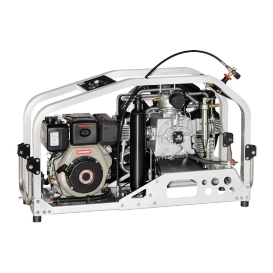
Page 9: Unit Assembly
D E S C R I P T I O N Unit Assembly Designation Filling Hose Carrying Handle Final Pressure Gauge Filter Housing Filling Valve LW 300 D MC A - 7 Version: 19.06.2017... -
Page 10: Start Device
D E S C R I P T I O N Start Device Fig. - Hand Start LW 300 D MC Fig. - Key Switch LW 300 D MC Designation Hand Start E-Starter (Key Switch) LW 300 D MC A - 8... -
Page 11: Flow Chart
1. Air Intake Filter 10. Oil-/Water Separator 19. Distributor Block 2. 1st Pressure Stage 11. 3rd Pressure Stage 20. Hose Pressure Gauge 3. Safety Valve 1st Stage 12. Endpressure-Safety Valve 21. Pressure Gauge (Filling Pressure) 4. Cooling Pipe 1st Stage 13. -
Page 12: Safety Precautions
S A F E T Y P R E C A U T I O N S... -
Page 13: Intended Use / Operators
Only trained personnel are permitted to work on the unit! Warning Work on the electrical equipment on / with the machine / unit may only be carried out by qualified electricians. LW 300 D MC A - 11 Version: 19.06.2017... -
Page 14: Safety Instructions On The Unit
Safety Instructions on the Unit Importance of notes and warning signs that are affixed to the compressor according to the application or its equipment. Note Warning Ensure correct direction of High voltage! rotation! Warning surfaces! LW 300 D MC A - 12 Version: 19.06.2017... -
Page 15: General Safety Precautions
• Do not use the product in areas prone to explosion or in the presence of flammable gases. The product is not designed for these applications. An explosion might be the result if certain conditions apply. LW 300 D MC A - 13 Version: 19.06.2017... -
Page 16: Unit Customised Safety Notices
• Soundproofing equipment on the compressor has to be activated in safety function during operation. • When handling with fats, oils and other chemical agents, observe the note for the product- related safety. LW 300 D MC A - 14 Version: 19.06.2017... -
Page 17: Maintenance Instructions
• Only personnel with particular knowledge and experience with pneumatics may carry out work on pneumatic equipment. • Only personnel with particular knowledge and experience in gas equipment may carry out work on gas equipment. LW 300 D MC A - 15 Version: 19.06.2017... -
Page 18: Transportation Instructions / Safety Regulations
• Inspections according to legal and local obligatory regulations regarding accident prevention are carried out by the manufacturer or by authorised expert personnel. No guarantees whatsoever are valid for damage caused or favoured by the non-consideration of these directions for use. LW 300 D MC A - 16 Version: 19.06.2017... -
Page 19: Installation
I N S T A L L A T I O N... -
Page 20: Outdoor Installation
Position compressor in direction of wind so that exhaust fumes are blown away from the unit. • Intake air must be free from noxious gas e.g. smoke, solvent vapours, exhaust fumes etc. • Observe the specified operating temperature (see "Technical Data")! LW 300 D MC A - 18 Version: 19.06.2017... -
Page 21: Dimensions
I N S T A L L A T I O N Dimensions Fig. - Dimensions LW 300 D MC A - 19 Version: 19.06.2017... -
Page 22: Minimum Distances
Front side min. 1500 mm, sides min. 500 mm, rear side min. 500 mm. Avoid anything in this area which can restrict the cooling air flow. 1500 Fig. - Minimum distances LW 300 D MC A - 20 Version: 19.06.2017... -
Page 23: Ventilation
O P E R A T I O N... -
Page 24: Electrical Installation
Note Ensure that all persons handling the compressor are familiar with function and operation of the unit. Wear hearing protection When working on a running machine, always wear hearing protection. LW 300 D MC A - 22 Version: 19.06.2017... -
Page 25: First Commissioning
• Check if the filter cartridge is in place (see "Service and Maintenance"). • Check the V-belt tension. • Read carefully the handbook of the petrol engine. • Check if all filling valves are closed. Open one filling valve and hold tight manually! LW 300 D MC A - 23 Version: 19.06.2017... - Page 26 F I R S T C O M M I S S I O N I N G Start the Compressor (LW 300 D MC) Open condensate valves Open fuel tab (Fig.3) Open filling valve Slide throttle lever (Fig.2) Start the compressor with the key switch or hand start (Fig.1).
-
Page 27: First Commissioning
Settings Motor Type Initial Installation Operation after running in Drive Motor LW 300 D MC 500N 400N LW 300 D MC A - 25 Version: 19.06.2017... -
Page 28: Daily Commissioning
• Check compressor oil level by using the oil dipstick. • Check if filter cartridge is in place / observe filter cartridge life! • Check fuel capacity. • Check drive motor oil level. • Ensure toxic-free, pure intake air. LW 300 D MC A - 26 Version: 19.06.2017... -
Page 29: Filling Procedure
Fill the compressed air cylinders to the desired pressure; subsequently close the filling valves slowly. Switch off the compressor. Close and vent all filling valves. Disconnect all compressed air cylinders from filling valves. 10. Open condensate drain valves manually. LW 300 D MC A - 27 Version: 19.06.2017... -
Page 30: Switch Off The Compressor
During filling process, the system can be shut down at every time by using the key switch or close the fuel tap. Note After switching off, open condensate drain valves manually to vent the unit. LW 300 D MC A - 28 Version: 19.06.2017... -
Page 31: Remedying Faults
R E M E D Y I N G F A U L T S... - Page 32 Clean, replace if necessary Cylinder(s), piston(s) or piston ring(s) used up Replace V-belt slips Tension V-belt See chapter "Final pressure can not be reached" See chapter "Final pressure can not be reached" LW 300 D MC A - 30 Version: 19.06.2017...
- Page 33 Cause of fault Remedy Mole carbon filter cartridge saturated Replace Compressor oil unsuitable Use prescribed oil quality Filter cartridge unsuitable Use prescribed filter type Cylinder(s), piston(s) or piston ring(s) defective Replace LW 300 D MC A - 31 Version: 19.06.2017...
- Page 34 Fuse / circuit breaker has tripped Check fusing of the power supply / observe Valid only for E models regulations Emergency stop switch has tripped Unlock emergency stop switch, close compressor housing door correctly LW 300 D MC A - 32 Version: 19.06.2017...
- Page 35 Use prescribed oil quality Operating temperature too high Observe prescribed operating temperatures Oil leak at the compressor block Tighten corresponding mounting screws, if necessary replace corresponding paper sealing / o-ring / shaft seal LW 300 D MC A - 33 Version: 19.06.2017...
-
Page 36: Maintenance And Service
M A I N T E N A N C E A N D S E R V I C E... -
Page 37: Service, Repair And Maintenance
Carry out maintenance or service work when the unit is switched off and protected against unexpected restart. Warning Risk of burns! Carry out maintenance or service work when the unit has cooled down. LW 300 D MC A - 35 Version: 19.06.2017... -
Page 38: Maintenance Lists / Maintenance Intervals
Quantity Order No. Oil change 000001 Every 3 months or as required Maintenance work Type Quantity Order No. Check automatic condensate drain, open manual condensate taps Check/Retorque all connections and bolts LW 300 D MC A - 36 Version: 19.06.2017... - Page 39 Check pressure maintaining/non-return valve Check V-belt tension and condition Note All stated quantities are parts of our 1000h, 2000h and 4000h service kits. You can find an overview on page Service Kits. LW 300 D MC A - 37 Version: 19.06.2017...
- Page 40 M A I N T E N A N C E A N D S E R V I C E Every 1000 operating hours Maintenance work Type Quantity Order No. Replace V-belt LW 300 D MC 009820 Replace sintered metal filter element of water after 2nd stage 002123 separators Replace o-rings of water separators...
- Page 41 007902 Replace needle bearings for conrod 007978 2nd and 3rd stage Note All stated quantities are parts of our 4000h service kits. You can find an overview on page Service Kits. LW 300 D MC A - 39 Version: 19.06.2017...
-
Page 42: Service Kits
O-Rings, Sinter Filter, Inlet Filter, V-Belts, Silencers, In-&Outlet Valve, Valve Seals and Compressor oil. Fig. - Service Kits Service Kits for LW 300 D MC Compressor Operating Hours Order No. LW 300 D MC... -
Page 43: Check V-Belt Tension / Tension V-Belt
• Tension V-belt (check V-belt tension after 1 hour use) • Tighten mounting nuts The V-belt change is now completed. Settings Motor Type Initial Installation Operation after running Drive Motor LW 300 D MC 500N 400N LW 300 D MC A - 41 Version: 19.06.2017... -
Page 44: Compressor Lubrication / Check Oil Level
Oil dipstick / Oil fillfill port Oil filter Oil Pressure Switch Low Pressure Oil Pump Oil drain hose with oil drain valve Fig. - Lubricating System LW 300 D MC A - 42 Version: 19.06.2017... -
Page 45: Check Oil Level
If there is too much oil inside, Fig. - Oil dipstick drain the oil surplus. If the oil level is too low, refill immediately new full synthetic compressor oil. Fig. - Marking LW 300 D MC A - 43 Version: 19.06.2017... -
Page 46: Oil Change
• All further changes after each 1,000 operating hours. Oil and oil capacity Approx. 1800 ml synthetic compressor oil is necessary for one oil change. Only use synthetic compressor oil which is recommended as suitable from L&W. LW 300 D MC A - 44 Version: 19.06.2017... -
Page 47: Oil Sieve Change
• We recommend cleaning or replacing the oil sieve every 1,000 working hours. • Service Kit oil pump (002569). Consists of: 000798—Oil sieve + 000672—oil pump cover gasket Fig. 1 Fig. 2 Correct oil sieve mounting direction LW 300 D MC A - 45 Version: 19.06.2017... -
Page 48: Oil Filter Maintenance
• Fix and tighten mounting nuts of the filter cover (Fig. 1). The oil filter maintenance is now completed. Fig. 1 - Loosen mounting nuts Fig. 2 - Change o-ring Fig. 3 - Change filter element Fig. 4 - Change gasket LW 300 D MC A - 46 Version: 19.06.2017... -
Page 49: Maintenance And Service
All oil / water separators have an integrated sinter filter which has to be replaced every 1,000 operating hours. Fig. 3 - Condensate drain valve LW 300 D MC A - 47 Version: 19.06.2017... -
Page 50: Oil / Water Separators 2Nd Stage - Maintenance
• Connect pipe connections and tighten. The oil / water separator maintenance is now completed. Fig. 2 - Remove sinter filter holder Fig. 3 - Change sinter filter Fig. 4 - Change o-ring LW 300 D MC A - 48 Version: 19.06.2017... -
Page 51: Filter Housing / Filter Cartridge
Filter Housing 001459 LW 300 D MC (Option) DIN EN 12021 (Breathing Air) incl. CO/CO2 0,54 ltr The high-pressure compressor is equipped with an integrated breathing air purification system. Air is compressed up to 350 bar, dried and odour- and tasteless purified. Oil residues are bounded. -
Page 52: Filter Cartridge Change Lw 300 D Mc
Do not run the compressor with empty unfilled cartridges. Only use genuine L&W cartridges. Filter Cartridge Change LW 300 D MC Change filter cartridge as follows: • Stop the compressor and carefully open the drain valves. Wait till the filter housing is completely vented;... -
Page 53: Filter Housing - Maintenance
• Screw the filter housing cover in by using the filter tool (Fig. 1). The filter housing maintenance is now completed. Fig. 1 - Remove/screw in filter cover Fig. 2 - Change o-ring LW 300 D MC A - 51 Version: 19.06.2017... -
Page 54: Inlet Filters / Inlet Filter Cartridge Change
• Refit cover and snap the three clips until a loud ‘click’ can be heard. The inlet filter cartridge change is now completed. Clips Cover Filter cartridge inlet filter Fig. - Filter cartridge inlet filter LW 300 D MC A - 52 Version: 19.06.2017... -
Page 55: Cylinder Heads And Valves
There are no special tools required to replace these valves. Available special tools Special tools are not necessary for dismounting inlet and outlet valves but make work easier. Order number: 006847 Fig. - Special tool LW 300 D MC A - 53 Version: 19.06.2017... -
Page 56: Fan Protection Cover Dismantling / Mounting The Fan Protection Cover
• Use the hole in the protection cover with the fixing stud • Tighten top mounting screws (Fig. 1). The fan protection cover mounting is now completed. Fig. 2 - Fixing stud LW 300 D MC A - 54 Version: 19.06.2017... -
Page 57: Replace Inlet And Outlet Valve 1St Stage
Fig. 4 - Loosen pipe connections Fig. 5 - Remove cooling pipe bracket Fig. 6 - Remove special hexagon bolt Fig. 7 - Remove valve head Continued on the following page LW 300 D MC A - 55 Version: 19.06.2017... - Page 58 The inlet and outlet valve change is now completed. Fig. 2 - Correct mounting position of upper valve gasket Fig. 3 - Place valve head to cylinder Fig. 4 - Tighten mounting screws Fig. 5 - Tighten pipe connections LW 300 D MC A - 56 Version: 19.06.2017...
-
Page 59: Replace Inlet And Outlet Valve 2Nd Stage
Fig. 2– clamp of cooling pipe Fig. 3 - Loosen pipe connections Fig. 4 - Remove cooling pipe bracket Fig. 5 - Remove cylinder bolts Fig. 6 - Remove valve head Continued on the following page LW 300 D MC A - 57 Version: 19.06.2017... -
Page 60: Replace Inlet And Outlet Valve 2Nd Stage
The inlet and outlet valve change is now completed. Fig. 2 - Correct mounting position of upper valve gasket Fig. 3 - Place valve head to cylinder Fig. 4 - Tighten mounting screws Fig. 5 - Tighten pipe connections LW 300 D MC A - 58 Version: 19.06.2017... -
Page 61: Replace Inlet And Outlet Valve 3Rd Stage
Fig. 2 - Loosen valve head screws Fig. 3 - Remove lower valve gasket Fig. 4 - Remove inlet and outlet valve Fig. 5 - Ensure correct mounting position of the upper valve gasket LW 300 D MC A - 59 Version: 19.06.2017... -
Page 62: Safety Valves
If a safety valve blows off, it indicates problems with either inlet or outlet valve of the following stage. Note Replace defective safety valves immediately! Fig. - Safety valve 3rd stage LW 300 D MC A - 60 Version: 19.06.2017... -
Page 63: Pressure Maintaining / Non Return Valve
The non return valve which is placed after the pressure maintaining valve, prevents the purified breathing air from flowing back into the filter housing / condensate drain valves. After compressor stop, the indicated filling pressure remains constant, if the non return valve is working correctly. LW 300 D MC A - 61 Version: 19.06.2017... -
Page 64: Adjust Pressure Maintaining Valve
(final pressure = 0 bar). When valve settings are not clear (e.g. after disassembly / repair), start the adjustment with a low basic setting (turn adjusting bolt 3 full turns in). LW 300 D MC A - 62 Version: 19.06.2017... -
Page 65: O-Rings-Filling Valve And Filling Hose
• Change o-ring, previously grease new o-ring • Connect filling hose to the filling valve and tighten Fig. 1 - O-ring at the filling valve Fig. 2 - O-ring at the filling hose LW 300 D MC A - 63 Version: 19.06.2017... -
Page 66: Test Of Pressure Equipment
The test methods described in point 1 and 2 must be repeated periodically - as described above. Max. numbers of load cycles for operation with max. allowable pressure variation Final pressure [bar] Load cycles Operating hours [h] 43750 10930 4400 1100 LW 300 D MC A - 64 Version: 19.06.2017... -
Page 67: Maintenance Records
M A I N T E N A N C E R E C O R D S... - Page 68 By adding themselves to this list, the person that signs it confirms having been given a yearly introduction/instruction about the function and operation of the compressor unit.Furthermore, they have be informed about the relevant safety rules and regualtions (TRG, DGRL, BetrSichV, GSG, GSGV). LW 300 D MC A - 66 Version: 19.06.2017...
- Page 69 M A I N T E N A N C E R E C O R D S Top up oil, oil change Date Operating hours Oil quantity [l] Name LW 300 D MC A - 67 Version: 19.06.2017...
- Page 70 M A I N T E N A N C E R E C O R D S Cartridge change Date Operating hours Difference Name LW 300 D MC A - 68 Version: 19.06.2017...
- Page 71 M A I N T E N A N C E R E C O R D S Maintenance work Description Date, signature LW 300 D MC A - 69 Version: 19.06.2017...
- Page 72 M A I N T E N A N C E R E C O R D S Replaced Parts Designation Part number Date, signature LW 300 D MC A - 70 Version: 19.06.2017...
-
Page 73: Storage
• Check the correct safety valve setting and/or pressure switch setting (option). • Check all connections and pipe work for leaks, retighten if necessary. Once the above steps are completed to satisfaction, the unit is ready to use. LW 300 D MC A - 71 Version: 19.06.2017... -
Page 74: Transportation Instructions / Disposal
The device can be returned to L&W. Please do not hesitate to contact us if you have any further questions on this issue. LW 300 D MC A - 72 Version: 19.06.2017... - Page 75 LW 300 D MC The new MC Series from L&W has been created for dive centers, ships, boats and places with limited space. These are suitable for continuous operation and guarantee low maintenance costs due to long service intervals. Comes ready to start. A super lightweight aluminum frame enables mobile applications, combined with very high filling capacity.
-
Page 76: Specifications
LW 300 D MC Specifications » Diesel Engine » Painted lightweight aluminium frame in RAL 7001 » Hour counter » Manual condensate drain » 1 x Filling hose c/w filling valve » Pressure maintaining and non return valve » All pistons c/w steel piston rings »... - Page 77 E R S A T Z T E I L L I S T E N / S PA R E PA R T S L I S T S D E TA I L A N S I C H T E N / D E TA I L E D V I E W S...
- Page 78 D E T A I L A N S I C H T / D E T A I L E D V I E W Gesamtansicht Kompressor / Overall View Compressor Version: 20.10.2016 LW 300 D MC S/S C - 3...
- Page 79 D E T A I L A N S I C H T / D E T A I L E D V I E W Gesamtansicht Verdichtereinheit / Overall View Compressor Assembly Version: 03.02.2015 LW 300 D MC S/S C - 4...
- Page 80 009231 Motorkonsole D-Version Motor Console 009234 Quertraverse Transv. traverse (motor side) 009865 Zylinderschraube Allen Bolt 009873 Linsenflanschschraube Lens Head Screw 009874 Linsenflanschschraube Lens Head Screw 009875 Linsenflanschschraube Lens Head Screw Version: 20.10.2016 LW 300 D MC S/S C - 5...
- Page 81 Benennung Description 009876 Linsenflanschschraube Lens Head Screw 009877 Linsenflanschschraube Lens Head Screw 009893 Lenkrolle 2477 PJO 100 P30-11 Swivel castor with lock 009894 Lenkrolle 2470 YGO 100 P30-11 Swivel castor Version: 20.10.2016 LW 300 D MC S/S C - 6...
- Page 82 D E T A I L A N S I C H T / D E T A I L E D V I E W Baugruppe: Grundgestell / Assembly: Main Frame Version: 20.10.2016 LW 300 D MC S/S C - 7...
- Page 83 D E T A I L A N S I C H T / D E T A I L E D V I E W Baugruppe: Grundgestell / Assembly: Main Frame Version: 20.10.2016 LW 300 D MC S/S C - 8...
- Page 84 Plug-on Fan Cover 008530 Eingriffschutz 2 Lüfterabdeckung Safety Guard 2 008884 Aufsteckstutzen Lüfterabdeckung Plug-on Fan Cover 009235 Aufkleber "LW 300 D MC" Sticker "LW 300 D MC" 009236 Lüfterabdeckung mit Schutzgitter Fan Guard complete 009877 Linsenflanschschraube Lens Head Screw 009878...
- Page 85 D E T A I L A N S I C H T / D E T A I L E D V I E W Baugruppe: Lüfterabdeckung / Assembly: Fan Guard Version: 20.10.2016 LW 300 D MC S/S C - 10...
- Page 86 D E T A I L A N S I C H T / D E T A I L E D V I E W Baugruppe: Lüfterabdeckung / Assembly: Fan Guard Version: 20.10.2016 LW 300 D MC S/S C - 11...
- Page 87 Press. Gauge c/w fixing strap Befestigungsbügel 005960 Zylinderschraube Allen Bolt 006002 U-Scheibe Washer (s/s) 007694 Blende für Einbaumanometer Ø63 mm Cover Bezel for Ø63 mm gauges 008389 Quertraverse Füllventil Transv. traverse (fil. valve) Version: 19.06.2017 LW 300 D MC S/S C - 12...
- Page 88 D E T A I L A N S I C H T / D E T A I L E D V I E W Baugruppe: Quertraverse Füllventil / Assembly: Transverse Traverse Filling Valve Version: 19.06.2017 LW 300 D MC S/S C - 13...
- Page 89 Taper Lock bush 009245 Schraube mit Scheibe Screw with Washer 009247 Antriebsmotor 7,4kW Diesel Engine 7,4kW 009279 Auspuff Exhaust LW 300 D MC 009281 Gelenkbolzenschelle 40 - 43mm Hinge Bolt Clamp 009820 Keilriemen V-Belt LW 300 D MC 009880 6kt-Schraube...
- Page 90 D E T A I L A N S I C H T / D E T A I L E D V I E W Baugruppe: Motor / Assembly: Engine Version: 20.10.2016 LW 300 D MC S/S C - 15...
- Page 91 005856 Winkeleinschraubverschraubung 8 Elbow Hose Connection 8 mm 005968 Zylinderschraube Allen Bolt 005969 Zylinderschraube Allen Bolt 005970 Zylinderschraube Allen Bolt 005975 6-kant Schraube Hexagon Bolt 005977 6-kant Schraube Hexagon Bolt Version: 19.06.2017 LW 300 D MC S/S C - 16...
- Page 92 Cylinder 3rd Stage 007943 Führungskolben 2.Stufe Guide Piston 2nd Stage 007944 Kolbenbolzen 2. & 3. Stufe Piston Pin, 2.+3. Stage 007945 Obere Ventildichtung für Ventil Upper Valve Gasket, Paper, 2nd 2.Stufe Version: 19.06.2017 LW 300 D MC S/S C - 17...
- Page 93 Upper Holder Fan Guard Lüfterabdeckung 008606 VA Rohr "Ölfilter-2.Stufe Pipe Führungszyl." 008607 VA Rohr "Ölfilter-3.Stufe Pipe Führungszyl." 008650 Druckfeder Ölfilter Coil Spring - oil filter 009869 Zylinderschraube Allen Bolt 009870 Zylinderschraube Allen Bolt Version: 19.06.2017 LW 300 D MC S/S C - 18...
- Page 94 D E T A I L A N S I C H T / D E T A I L E D V I E W Baugruppe: Kompressorblock / Assembly: Compressor Block Version: 19.06.2017 LW 300 D MC S/S C - 19...
- Page 95 Pleuel 1.Stufe Conrod c/w Needle Bearing 008794 Pleuel 2. & 3. Stufe Conrod c/w Needle Bearings 008795 Kurbelwelle, inkl. Gegengewicht Crankshaft with Counter Weight 008796 Kurbeltrieb komplett Crank Drive complete Version: 03.02.2015 LW 300 D MC S/S C - 20...
- Page 96 D E T A I L A N S I C H T / D E T A I L E D V I E W Baugruppe: Kurbeltrieb / Assembly: Crank Drive Version: 03.02.2015 LW 300 D MC S/S C - 21...
- Page 97 Baugruppe: Kolben 1. Stufe / Assembly: Piston 1st Stage Best.-Nr. / Order No. Benennung Description 007973 Kolben inkl. Kolbenringe, Bolzen 1. St. Piston, compl. 1st Stage 008799 Kolbenringe 1.Stufe Satz Piston Rings 1st Stage Version: 03.02.2015 LW 300 D MC S/S C - 22...
- Page 98 D E T A I L A N S I C H T / D E T A I L E D V I E W Baugruppe: Kolben 1. Stufe / Assembly: Piston 1st Stage Version: 03.02.2015 LW 300 D MC S/S C - 23...
- Page 99 Baugruppe: Kompressionskolben 2. Stufe / Assembly: Compression Piston 2nd Stage Best.-Nr. / Order No. Benennung Description 008800 Kolbenringe 2.Stufe Satz Piston Rings 2nd Stage 008802 Kompressionskolben 2.Stufe Compression Piston 2nd Stage Version: 03.02.2015 LW 300 D MC S/S C - 24...
- Page 100 D E T A I L A N S I C H T / D E T A I L E D V I E W Baugruppe: Kompressionskolben 2. Stufe / Assembly: Compression Piston 2nd Stage Version: 03.02.2015 LW 300 D MC S/S C - 25...
- Page 101 Baugruppe: Kompressionskolben 3. Stufe / Assembly: Compression Piston 3rd Stage Best.-Nr. / Order No. Benennung Description 008801 Kolbenringe 3.Stufe Satz Piston Rings 3rd Stage 008803 Kompressionskolben 3.Stufe Compression Piston 3rd Stage Version: 03.02.2015 LW 300 D MC S/S C - 26...
- Page 102 D E T A I L A N S I C H T / D E T A I L E D V I E W Baugruppe: Kompressionskolben 3. Stufe / Assembly: Compression Piston 3rd Stage Version: 03.02.2015 LW 300 D MC S/S C - 27...
- Page 103 Baugruppe: Saug & Druckventil 1. & 2. Stufe / Assembly: In & Outlet Valve 1st & 2nd Stage Best.-Nr. / Order No. Benennung Description 007912 Saug-Druckventil 2. Stufe In & Outlet Valve 2nd Stage 007913 Saug-Druckventil 1. Stufe In & Outlet Valve 1st Stage Version: 03.02.2015 LW 300 D MC S/S C - 28...
- Page 104 D E T A I L A N S I C H T / D E T A I L E D V I E W Baugruppe: Saug & Druckventil 1. & 2. Stufe / Assembly: In & Outlet Valve 1st & 2nd Stage Version: 03.02.2015 LW 300 D MC S/S C - 29...
- Page 105 Ventildichtung, Saug-& Druckventil Lower Valve Gasket, 3rd Stage unten 000541 Dichtring / Dichtung Ventil 3.Stufe Upper Alloy Seal Ring 008823 Saug- & Druckventil, 3. Stufe komplett In- & Outlet Valve, 3rd Stage Version: 19.06.2017 LW 300 D MC S/S C - 30...
- Page 106 D E T A I L A N S I C H T / D E T A I L E D V I E W Baugruppe: Saug & Druckventil 3. Stufe / Assembly: In & Outlet Valve 3rd Stage Version: 19.06.2017 LW 300 D MC S/S C - 31...
- Page 107 Union Nut 18L 005955 Zylinderschraube Allen Bolt 005956 Zylinderschraube Allen Bolt 006001 U-Scheibe Washer (s/s) 008222 Rippenrohrkühler 1. Stufe Finned cooling pipe 1st Stage 008497 Rohrschelle Ø21 - 12 breit Pipe Clamp Version: 20.10.2016 LW 300 D MC S/S C - 32...
- Page 108 D E T A I L A N S I C H T / D E T A I L E D V I E W Baugruppe: Kühler 1. Stufe / Assembly: Cooler 1st Stage Version: 20.10.2016 LW 300 D MC S/S C - 33...
- Page 109 Kühlrohrklemme 2. Stufe Cooling Pipe Clamp 2. Stage 008223 Rippenrohrkühler 2.Stufe finned cooler pipe 2nd Stage 008497 Rohrschelle Ø21 Pipe Clamp Ø21 009867 Zylinderschraube DIN912 M6x45 Allen Bolt DIN912 M6x45 Version: 21.10.2016 LW 300 D MC S/S C - 34...
- Page 110 D E T A I L A N S I C H T / D E T A I L E D V I E W Baugruppe: Kühler 2. Stufe / Assembly: Cooler 2nd Stage Version: 21.10.2016 LW 300 D MC S/S C - 35...
- Page 111 Bracket for Cooling Pipe Clamp 008788 Kühlrohrklemme 3.Stufe 5-fach Cooling Pipe Clamp 5-fold 008857 Halterung Kühlrohrklemme 3. Stufe Bracket for Cooling Pipe Clamp 009866 Zylinderschraube Allen Bolt 009867 Zylinderschraube Allen Bolt Version: 21.10.2016 LW 300 D MC S/S C - 36...
- Page 112 D E T A I L A N S I C H T / D E T A I L E D V I E W Baugruppe: Kühler 3. Stufe / Assembly: Cooler 3rd Stage Version: 21.10.2016 LW 300 D MC S/S C - 37...
- Page 113 U-Scheibe Washer (s/s) 006005 U-Scheibe Washer (s/s) 007921 Ventilatorflügelblatt Fan blade 007923 Schwungrad Flywheel 008862 Haltering Ventilatorflügel (13 Stück) Fan blade Fixing Ring 009884 Schnorr-Scheibe Lock Washer 009886 U-Scheibe Washer Version: 21.10.2016 LW 300 D MC S/S C - 38...
- Page 114 D E T A I L A N S I C H T / D E T A I L E D V I E W Baugruppe: Lüfterrad / Assembly: Flywheel Assembly Version: 21.10.2016 LW 300 D MC S/S C - 39...
- Page 115 Holder for Sinterfilter G3/8" 003077 Entwässerungsventil G1/4" AG, konisch Drain valve G1/4" male 006031 Stoppmutter Lock Nut M8 006003 U-Scheibe A8 Washer A8 008482 Haltebügel für Wasserabweiser U-Clamp Water Separator Version: 24.10.2016 LW 300 D MC S/S C - 40...
- Page 116 D E T A I L A N S I C H T / D E T A I L E D V I E W Baugruppe: Wasserabscheider / Assembly: Water Separator Version: 24.10.2016 LW 300 D MC S/S C - 41...
- Page 117 Baugruppe: Ansaugfilter / Assembly: Intake Filter Best.-Nr. / Order No. Benennung Description 000170 Ansaugfilterpatrone Air Intake Filter Cartridge 000171 Ansaugfiltergehäuse inkl. Patrone, kompl Int. Filter Housing c/w filter 000201 Einschraubadapter Ansaugfilter Adapter Inlet Filter Housing Version: 03.02.2015 LW 300 D MC S/S C - 42...
- Page 118 D E T A I L A N S I C H T / D E T A I L E D V I E W Baugruppe: Ansaugfilter / Assembly: Intake Filter Version: 03.02.2015 LW 300 D MC S/S C - 43...
- Page 119 Benennung Description 000817 Verschraubung Connection 002153 Ölablassschlauch inkl. Kugelhahn Oil Drain Hose c/w Ball Valve 006964 Klemmhalter Ölablassschlauch Clamp Oil Drain Hose 005955 Zylinderschraube M5x16mm DIN912 Allen Screw M5x16mm DIN912 Version: 21.10.2016 LW 300 D MC S/S C - 44...
- Page 120 D E T A I L A N S I C H T / D E T A I L E D V I E W Baugruppe: Ölablassschlauch / Assembly: Oil Drainage Tube Version: 21.10.2016 LW 300 D MC S/S C - 45...
- Page 121 Hexagon Socket Screw M8x16mm DIN914 005962 Zylinderschraube Allen Bolt 002340 O-Ring Ölansaugadapter O-Ring, oil pump flange 007900 O-Ring O-Ring 008603 VA Rohr "Ölpumpe - Ölfilter" Pipe 008608 VA Rohr "Block - Ölpumpe" Pipe Version: 21.10.2016 LW 300 D MC S/S C - 46...
- Page 122 D E T A I L A N S I C H T / D E T A I L E D V I E W Baugruppe: Ölpumpe / Assembly: Oil Pump Version: 21.10.2016 LW 300 D MC S/S C - 47...
- Page 123 Sicherheitsventil - Bauteilgeprüft Safety Valve TÜV 225 bar 000556 Sicherheitsventil - Bauteilgeprüft Safety Valve TÜV 330 bar 001244 O-Ring O-Ring, flange safety valve 005970 Zylinderschraube M8x70mm DIN912 Allen Bolt M8x70mm DIN912 Version: 19.06.2017 LW 300 D MC S/S C - 48...
- Page 124 D E T A I L A N S I C H T / D E T A I L E D V I E W Baugruppe: Enddrucksicherheitsventil / Assembly: Final Safety Valve 330 bar Safety Valve 225 bar Safety Valve 000553 - Safety Valve 225 bar 000556 - Safety Valve 330 bar Version: 19.06.2017 LW 300 D MC S/S C - 49...
- Page 125 O P T I O N S...
- Page 126 T a b l e o f C o n t e n t s Auto Shut Down .......................... 2 Automatic Condensation Drain ....................7 Switch Over Device 200+300bar ....................21 Oil Pressure Gauge ........................27...
-
Page 127: Auto Shut Down
A U T O S H U T D O W N LW 300 D MC S/S D - 2... - Page 128 This considerably reduces the life of the safety valve. Example settings: Safety valve Max. Operating Pressure 225 bar 215 bar 250 bar 240 bar 330 bar 320 bar Version: 21.10.2016 LW 300 D MC S/S D - 3...
-
Page 129: Pressure Switch
Description 000203 Druckschalter, G1/4" IG, PV 50 - 350 bar Pressure Switch 50-350 bar 000757 T-Verschraubung T-Connection with fixed nut 000761 Winkel Verschraubung Connection 009683 Verschraubung Connection with fixed nut Version: 21.10.2016 LW 300 D MC S/S D - 4... - Page 130 Battery 12V, 9 Ah 008971 Kabeldurchführung Grommet 008974 Kabelschutzschlauch FPAS 28 Cable Protection Hose, 470mm 009234 Quertraverse Transv. traverse (motor side) 009238 Schlüsselschalter Keyswitch 009240 Halteblech Batterie Bracket, Battery 009867 Zylinderschraube Allen Bolt Version: 21.10.2016 LW 300 D MC S/S D - 5...
- Page 131 A U T O S H U T D O W N Baugruppe: Elektroschaltkasten / Assembly: Electro Box Version: 21.10.2016 LW 300 D MC S/S D - 6...
-
Page 132: Automatic Condensation Drain
A U T O M A T I C C O N D E N S A T I O N D R A I N LW 300 D MC S/S D - 7... - Page 133 The collected condensate can contain oil and has to be disposed according to regulations. Automatic condensation dump system is an option for LW 300 D MC . Solenoids drain all condensate separators every 15 minutes. To test the system, press the blue condensate test drain button on the operating panel.
- Page 134 • Tighten pipe connections and mounting screws. The oil / water separator maintenance is now completed. Fig. 1 - Loosen ring nut Fig. 2 - Change sinter filter Fig. 3 - Change o-ring Version: 19.06.2017 LW 300 D MC S/S D - 9...
- Page 135 • Mount pneumatic condensate valve. • Tighten pipe connections and mounting screws. Pneumatic Condensate Valve Pneumatic condensate valve maintenance is now completed. Fig. 2 - Loosen connection Fig. 3 - Change sinter filter Version: 19.06.2017 LW 300 D MC S/S D - 10...
- Page 136 Elbow Connection 003067 Kondensatschlauch 8x1mm Condensate hose 8x1mm Polyamid 008601 VA Rohr "Kondensatautom.- Pipe Ölabscheider" 008602 VA Rohr "Wasserabs 2.S.- Pipe Kondensatautom" 009863 VA Rohr "HD Filter - Pipe Kondensatautomatik" Version: 19.06.2017 LW 300 D MC S/S D - 11...
- Page 137 A U T O M A T I C C O N D E N S A T I O N D R A I N Overall View: Automatic Condensation Drain Version: 19.06.2017 LW 300 D MC S/S D - 12...
- Page 138 A U T O M A T I C C O N D E N S A T I O N D R A I N Overall View: Automatic Condensation Drain Version: 19.06.2017 LW 300 D MC S/S D - 13...
- Page 139 Zylinderschraube M6x55mm DIN912 Allen Bolt M6x55mm DIN912 000602 Sandwichtimer Timer 24-230V DC/AC 000710 Verschraubung Connection w/o nut& olive seal 000721 Verschraubung Connection 000738 Verschraubung Connection 001156 Stoppmutter M6 Lock Nut M6 Version: 19.06.2017 LW 300 D MC S/S D - 14...
- Page 140 A U T O M A T I C C O N D E N S A T I O N D R A I N Assembly: Pneumatic Condensate Valve Version: 19.06.2017 LW 300 D MC S/S D - 15...
- Page 141 Double Nipple 001546 Aludichtring für Magnetventile G1/4" Alloy Seal Ring for G1/4" male 004002 Magnetventil 40/80 bar Solenoid Valve, Housing: Brass 005855 Winkeleinschraubverschraubung 8 mm Elbow Hose Connection 8 mm Version: 19.06.2017 LW 300 D MC S/S D - 16...
- Page 142 Lock Nut M6 006031 Stoppmutter M8 Lock Nut M8 007972 Halterung Endabscheider Bracket final separator 008822 Kondensatabscheider Endstufe Water Separator 009864 Zylinderschraube Allen Bolt 009877 Linsenflanschschraube M8x25 lens head screw Version: 19.06.2017 LW 300 D MC S/S D - 17...
- Page 143 A U T O M A T I C C O N D E N S A T I O N D R A I N Assembly: Oil / Water Separators Final Stage Version: 19.06.2017 LW 300 D MC S/S D - 18...
- Page 144 Spring Clamping Plate CCT 008495 Filter Kondensatbehälter Filter Condensate Catch Tank 008655 Linsenflanschschraube M6x12mm Lens Head Screw M6x12mm 008680 Halteblech 10-Liter Kondensatbehälter Holder Condensate Catch Tank 10 Litre 008831 Verschlussstopfen Plug Version: 19.06.2017 LW 300 D MC S/S D - 19...
- Page 145 A U T O M A T I C C O N D E N S A T I O N D R A I N Assembly: Housing Condensate-Catch-Tank Version: 19.06.2017 LW 300 D MC S/S D - 20...
-
Page 146: Switch Over Device 200+300Bar
S W I T C H O V E R D E V I C E 2 0 0 / 3 0 0 B A R LW 300 D MC S/S D - 21... - Page 147 200 bar The pressure selector spindle (1) should be screwed fully out anti clockwise. Switch over Device ATTENTION Operate 200/300bar pressure selector spindle (1) only if filterhousing has been vented. Version: 21.10.2016 LW 300 D MC S/S D - 22...
- Page 148 6-kant Sicherungsmutter M8 Nylon Insert Lock Nut M8 (s/s) 006305 Hohlschraube Banjo Bolt 006306 Sterngriff Star Shaped Grip 006307 Verbindungsnippel Nozzle 006456 Verschlussstopfen G1/4" Plug 1/4" - s/s 007558 Verschraubung Connection Version: 21.10.2016 LW 300 D MC S/S D - 23...
- Page 149 Pipe Ø8mm (c/w nut & olive) Muttern&Schneidri. 009871 Zylinderschraube Allen Bolt 009872 Zylinderschraube Allen Bolt 009877 Linsenflanschschraube Lens Head Screw 009890 Winkelverschraubung Elbow Connection w. fixed Nut 009890 Winkelverschraubung Elbow Connection w. fixed Nut Version: 21.10.2016 LW 300 D MC S/S D - 24...
- Page 150 S W I T C H O V E R D E V I C E 2 0 0 / 3 0 0 B A R Switch Over Device 200/300bar Version: 21.10.2016 LW 300 D MC S/S D - 25...
- Page 151 S W I T C H O V E R D E V I C E 2 0 0 / 3 0 0 B A R Switch Over Device 200/300bar Version: 21.10.2016 LW 300 D MC S/S D - 26...
- Page 152 O I L P R E S S U R E G A U G E LW 300 D MC S/S D - 27...
- Page 153 If oil pressure value stays above the maximum value: • Low oil temperature, between +5 °C and +10 °C • Should stay within the range of tolerance when operation temperature is reached.. Version: 01.11.2015 LW 300 D MC S/S D - 28...
- Page 154 O I L P R E S S U R E G A U G E Spare part lists Best.-Nr. / Order No. Benennung Description 000655 Einbaumanometer mit Press.Gauge, glycerine, brass Befestigungsbügel 000721 Verschraubung Connection 008934 Manometerschlauch, Pressure Gauge Hose Minimeßschlauch Version: 01.11.2015 LW 300 D MC S/S D - 29...
- Page 155 A T T A C H M E N T Version: 11/12-E...
Need help?
Do you have a question about the LW 300 D MC and is the answer not in the manual?
Questions and answers