Table of Contents
Advertisement
C H A P T E R O V E R V I E W
Operating Instructions
..........................................................................................................................
Spare Parts Lists
Options (if equipped)
Attachment
....................................................................................................................................
Manufacturer in terms of 97/23/EC
The full name and address of the manufacturer is:
Lenhardt & Wagner GmbH
An der Tuchbleiche 39
68623 Hüttenfeld / Germany
Phone: +49 (0) 62 56 - 85 88 0 - 0
Fax: +49 (0) 62 56 - 85 88 0 - 14
E-Mail: service@lw-compressors.com
Internet: www.lw-compressors.com
Version: 11/12-E
..............................................................................................................
................................................................................................................
A
B
C
D
Advertisement
Chapters
Table of Contents

Related Manuals for L&W Compressors LW 100 E


Summary of Contents for L&W Compressors LW 100 E
- Page 1 C H A P T E R O V E R V I E W ......................Operating Instructions .......................... Spare Parts Lists Options (if equipped) ........................ Attachment ............................ Manufacturer in terms of 97/23/EC The full name and address of the manufacturer is: Lenhardt &...
- Page 2 S E R V I C E I N F O R M A T I O N / W A R R A N T Y Compressor information Type designation Serial number Date of construction Purchase information Purchase date First commissioned on Warranty period Dealer's stamp...
-
Page 3: Operating Instructions
Operating Instructions Breathing Air Compressor LW 100 series Version: 29.03.2016... -
Page 4: Table Of Contents
General Information / Description of Warning Symbols ..............4 Drive motors ............................5 Scope of Delivery LW 100 E (ECO) / LW 100 E1 (ECO) ................ 6 Scope of Delivery LW 100 B ECO / LW 100 B ..................7 Technical Data .......................... - Page 5 T A B L E O F C O N T E N T S Maintenance and Service Service, Repair and Maintenance ....................41 Maintenance Lists / Maintenance Intervals ................42 - 44 Service Kits ............................. 45 Check V-belt tension / Tension V-belt / Settings ................46 Compressor lubrication / Check oil level ..................
-
Page 6: General Information / Description Of Warning Symbols
G E N E R A L I N F O R M A T I O N General Information We strongly recommend reading this manual thoroughly prior to operation and follow all the safety precautions precisely. Damage resulting from any deviation from these instructions is excluded from warranty and liability for this product. -
Page 7: Drive Motors
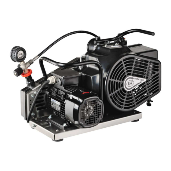
High performance Briggs & Stratton 4 gear motor (4.5 kW) with integrated fuel tank. Pull start, auto cut off at low oil level LW 100 E ECO / LW 100 E 2.2 kW E-Motor / 400V (230V/440V as an option) / 3 phase / 50 Hz (60 Hz as an option). -
Page 8: Scope Of Delivery Lw 100 E (Eco) / Lw 100 E1 (Eco)
D E S C R I P T I O N Scope of Delivery LW 100 E (ECO) / LW 100 E1 (ECO) Compressors are provided in different equipped versions. Versions Filling pressure versions: • PN 225 bar • PN 330 bar •... -
Page 9: Scope Of Delivery Lw 100 B Eco / Lw 100 B
D E S C R I P T I O N Scope of Delivery LW 100 B ECO / LW 100 B Compressors are provided in different equipped versions. Versions Filling pressure versions: • PN 225 bar • PN 330 bar •... -
Page 10: Technical Data
D E S C R I P T I O N Technical Data Technical Data LW 100 E / (ECO) LW 100 E1 / (ECO) LW 100 B / (ECO) Capacity [l/min]: Max. Operating Pressure [bar]: RPM [min 2300 2300... -
Page 11: Unit Assembly Lw 100 E / E1
D E S C R I P T I O N Unit Assembly LW 100 E / E1 Designation Pressure gauge Filling hose with filling valve Carrying handles (ECO Optional) E-Motor / 400V / 3 Phase / 50 Hz or E-Motor / 230V / single phase / 50Hz... -
Page 12: Unit Assembly Lw 100 B
D E S C R I P T I O N Unit Assembly LW 100 B Designation Pressure gauge Intake telescopic pipe Filling hose with filling valve Carrying handles (ECO Optional) 4 stroke gasoline engine, hand start LW 100 Series Page A - 10 Version: 29.03.2016... -
Page 13: Flow Chart
D E S C R I P T I O N Flow chart Air Intake Filter 13. Cooling Pipe Final Stage 1st Pressure Stage 14. Condensate Release Hose Safety Valve 1st Stage 15. Condensate Release Valve Cooling Pipe 1st Stage 16. -
Page 14: Safety Precautions
S A F E T Y P R E C A U T I O N S... -
Page 15: Intended Use / Operators
S A F E T Y P R E C A U T I O N S Intended Use Only use the unit in perfect condition for its intended purpose, safety and intended use and observe the operating instructions! In particular disorders that may affect safety have to be eliminated immediately! Use the unit exclusively for the determined medium (see "Technical Data"). -
Page 16: Safety Instructions On The Unit
S A F E T Y P R E C A U T I O N S Safety instructions on the unit Importance of notes and warning signs that are affixed to the compressor according to the application or its equipment. Warning Note High voltage! -
Page 17: General Safety Precautions
S A F E T Y P R E C A U T I O N S General Safety Precautions • Read the Operating Instructions of this product carefully prior to use. • Read the Operating Instructions of the petrol engine carefully prior to use. (LW 100 B Versions) •... -
Page 18: Unit Customised Safety Notices
S A F E T Y P R E C A U T I O N S Unit customised safety notices Organisational measures • In addition to the instruction manual, observe and comply with universally valid legal and other obligatory regulations regarding accident prevention and environment protection. •... -
Page 19: Maintenance Instructions
S A F E T Y P R E C A U T I O N S Maintenance instructions • Hoses have to be checked by the operator (pressure and visual inspection) at reasonable intervals, even if no safety-related defects have been detected. •... -
Page 20: Transportation Instructions / Safety Regulations
S A F E T Y P R E C A U T I O N S Transportation instructions • Parts which need to be dismantled for transport purposes must be carefully replaced and secured before taking into operation. • The transport may only be carried out by trained personnel. •... -
Page 21: Installation
I N S T A L L A T I O N... -
Page 22: Installation In Closed Rooms - Lw 100 E / E1
I N S T A L L A T I O N Installation in closed rooms - LW 100 E / E1 Danger No operation in explosion-hazard areas. The unit is not approved for operation in areas prone to explosion. -
Page 23: Installation Lw 100 B
I N S T A L L A T I O N Installation LW 100 B Danger Compressors with petrol or diesel motors must only be located outdoors, never indoors, not even in partially closed rooms however large they may be. For outside installation observe the following: •... -
Page 24: Dimensions
I N S T A L L A T I O N Dimensions LW 100 E / E1 Fig. Dimensions Dimensions LW 100 B Fig. Dimensions LW 100 Series Page A - 22 Version: 29.03.2016... -
Page 25: Minimum Distances
Front side min. 300 mm, rear side min. 300 mm. Avoid anything in this area which can restrict the cooling air flow. • No minimum distances are required at the side panels. 300 mm 300 mm Fig. Minimum distances LW 100 E / E1 300 mm 300 mm Fig. Minimum distances LW 100 B LW 100 Series Page A - 23 Version: 29.03.2016... -
Page 26: Ventilation Lw 100 E / E1
I N S T A L L A T I O N Ventilation LW 100 E / E1 • Make sure that the compressor always has a sufficient amount of fresh air available for cooling. • To prevent serious damage, ensure that the cooling air flow can flow freely. -
Page 27: Electrical Installation Lw 100 E / E1
• When connecting the unit to the electrical supply, check the compressor direction of rotation (see chapter "Operation -> First commisioning - LW 100 E/E1). • Fuse the motor correctly (see table; use slow-blow fuses). LW 100 Series Page A - 25 Version: 29.03.2016... -
Page 28: Electrical Installation Lw 100 E / E1
I N S T A L L A T I O N Electrical Installation LW 100 E / E1 The compressor comes fully wired with cable and plug. An installation is not necessary. Recommended fuses for 360 - 500 V operating voltage... -
Page 29: Operation
O P E R A T I O N... -
Page 30: Important Operation Instructions
O P E R A T I O N Important operation instructions Danger On petrol or diesel engines, operation unit must only be located outdoors, never indoors, not even in partially closed rooms however large they may be. Note Ensure that all persons handling the compressor are familiar with function and operation of the unit. -
Page 31: First Commissioning Lw 100 E / E1
F I R S T C O M M I S S I O N I N G - L W 1 0 0 E / E 1 Prior to first commissioning, observe the following: • Ensure that cooling air can flow freely. •... -
Page 32: First Commissioning Lw 100 E / E1
F I R S T C O M M I S S I O N I N G - L W 1 0 0 E / E 1 Check turning direction - LW 100 E Warning Wrong impeller rotation direction! Immediately after switching the compressor on, check rotation direction. -
Page 33: First Commissioning Lw 100 B
F I R S T C O M M I S S I O N I N G - L W 1 0 0 B Prior to first commissioning, observe the following: • Ensure that cooling air can flow freely. •... -
Page 34: Daily Commissioning
D A I L Y C O M M I S S I O N I N G Prior to daily operation observe the following: LW 100 E / E1 • Ensure cooling air can flow freely. • Check the compressor oil level by the oil dipstick. -
Page 35: Filling Procedure
O P E R A T I O N Filling procedure Caution! Fill only cylinders which: - are marked with the test mark and the test stamp of the expert. - have been hydrostatic tested (check last test date). - are rated for the final pressure. - are free from humidity. -
Page 36: Switch Off The Compressor
During filling process, the system can be shut down at any time by pushing the OFF - button (OFF) . Switch off the compressor unit LW 100 E / E1 • Stop compressor by the toggle switch (OFF). -
Page 37: Remedying Faults
R E M E D Y I N G F A U L T S... - Page 38 R E M E D Y I N G F A U L T S Final pressure can not be reached Cause of fault Remedy Connections leaky Retighten or clean/replace if necessary Final pressure safety valve leaky Replace, turn out vent screw if necessary Pipes / heat exchanger broken Replace Condensate drain valves leaky...
- Page 39 R E M E D Y I N G F A U L T S Compressor overheated Cause of fault Remedy Inlet filter cartridge contaminated Replace Ambient temperature too high Improve room ventilation / Reduce operation times Cooling air inlet and outlet insufficient Observe minimum distances (see Installation Instructions) Air intake hose too long...
- Page 40 R E M E D Y I N G F A U L T S Automatic condensate drain defective Only valid with the option - Automatic Condensate Drain Cause of fault Remedy Solenoid coils defective Replace Cable / supply cable defective Repair, replace if necessary Timer / relais defective Replace...
- Page 41 R E M E D Y I N G F A U L T S Filter life not sufficient Cause of fault Remedy Pressure maintaining valve settings not correct Adjust as prescribed Filter cartridge unsuitable Replace by a prescribed filter cartridge type Filter cartridge too old Observe expiration date Filter cartridge packaging incorrect / damaged /...
-
Page 42: Maintenance And Service
M A I N T E N A N C E A N D S E R V I C E... -
Page 43: Service, Repair And Maintenance
M A I N T E N A N C E A N D S E R V I C E Service, Repair and Maintenance Carry out service and maintenance work exclusively when the compressor is stopped and depressurised. The unit should be leak-checked regularly. Leaks can be preferably localised by using a leak detector spray (if necessary, brush pipes with soapy water). -
Page 44: Maintenance Lists / Maintenance Intervals
Maintenance work Type Quantity Order No. Check oil level 000001 Check condition of all filling hoses LW 100 E 000644 Check filter cartridge lifetime LW 100 B 002309 Operate unit to final pressure and check function of final pressure switch... - Page 45 000001 Clean oil/water separators Every 500 operating hours Maintenance work Type Quantity Order No. Replace V-belt LW 100 E/E1 (50Hz) 001842 LW 100 E/E1 (60Hz) 001701 LW 100 B (B&S) 008503 LW 100 B (Honda) 001803 Replace o-ring of the DIN filling connector...
- Page 46 M A I N T E N A N C E A N D S E R V I C E Every 1000 operating hours Maintenance work Type Quantity Order No. Replace o-rings and gaskets of Gasket (1st stage) 001705 1st, 2nd and 3rd stage O-Ring (1st stage) 001781...
-
Page 47: Service Kits
Depending on the model and interval, the service kits include parts such as O-Rings, Sinter Filter, Inlet Filter, V-Belts, Silencers, In-&Outlet Valve, Valve Seals and Compressor oil. Service Kits Service Kits LW 100 E / E1 for 50 Hz Compressor Frequency Operating Hours Order No. -
Page 48: Check V-Belt Tension / Tension V-Belt / Settings
M A I N T E N A N C E A N D S E R V I C E Check V-belt tension The compressors of all LW 100 versions are driven by V-belts. Check correct V-belt tension regularly, adjust if necessary. -
Page 49: Compressor Lubrication / Check Oil Level
M A I N T E N A N C E A N D S E R V I C E Compressor Lubrication Pistons, cylinders, crankshaft and connecting rods are provided with oil by splash lubrication. Check oil level Warning Check oil level daily. -
Page 50: Oil Change
M A I N T E N A N C E A N D S E R V I C E Oil change Note We recommend oil change at least once a year - depending on total operating hours. Oil change as follows: •... -
Page 51: Manual Condensation Dump System
M A I N T E N A N C E A N D S E R V I C E Manual condensation dump system Note The collected condensate can contain oil and has to be disposed according to regulations. Oil- / water separators The compressor comes as standard with a manual condensation dump system. -
Page 52: Oil / Water Separators 2Nd Stage - Maintenance
M A I N T E N A N C E A N D S E R V I C E Oil / water separators 2nd stage - maintenance Note Clean all parts thoroughly before assembly. Maintenance / cleaning of oil / water separators 2nd stage as follows: •... -
Page 53: Filter Housing / Filter Cartridge
• 18 hours for LW 100 E ECO / LW 100 E1 ECO / LW 100 E / LW 100 E1 (Order No.: 000644) • 16 hours for LW 100 B ECO / LW 100 B (Order No.: 002309) -
Page 54: Filter Cartridge Change
Ensure that the old filter cartridge is disposed correctly at an approved waste point. Fig. 2 - Remove filter housing cover Filtering Models 000644 DIN EN 12021 LW 100 E/E1 ECO LW 100 E/E1 (Breathing Air) 002309 DIN EN 12021 LW 100 B ECO LW 100 B (Breathing Air) inkl. -
Page 55: Filter Housing - Maintenance
M A I N T E N A N C E A N D S E R V I C E Filter housing - maintenance Note Clean all parts thoroughly before assembly. Filter housing maintenance as follows: • Unscrew filter housing cover by using the filter tool (Fig. 1). •... -
Page 56: Inlet Filter
M A I N T E N A N C E A N D S E R V I C E Inlet Filter Note Dirty filters make air intake difficult and reduce delivery capacity. Risk of compressor overheating. A paper dry filter is used for the inlet filter. Check air inlet filter regularly or replace it. -
Page 57: Check Or Change Filter Inlet
M A I N T E N A N C E A N D S E R V I C E Check or change filter inlet Note Clean all parts thoroughly before assembly. To properly change the filter inlet, proceed as follows: •... -
Page 58: Valve Heads And Valves / Pistons And Cylinders / Cooling
M A I N T E N A N C E A N D S E R V I C E Valve heads and valves Inlet and outlet valves of the specific compressor stages are located between valve head and cylinder. Inlet valves open while piston downstroke;... -
Page 59: Replace Inlet And Outlet Valve 1St Stage
M A I N T E N A N C E A N D S E R V I C E Replace inlet and outlet valve 1st stage Note The figures of the parts can differ due to the different stages. Replace the inlet and outlet valve 1st stage as follows: Remove inlet / outlet valve •... -
Page 60: Replace Inlet And Outlet Valve 1St Stage
M A I N T E N A N C E A N D S E R V I C E Replace inlet and outlet valve 1st stage - continued from previous page Warning The exact alignment of upper and lower valve gasket is very important. Inlet and outlet channels have to be exactly centred. -
Page 61: Replace Inlet And Outlet Valves 2Nd And 3Rd Stage
M A I N T E N A N C E A N D S E R V I C E Replace inlet and outlet valves 2nd and 3rd stage Note The figures of the parts can differ due to the different stages. Inlet and outlet valves change as follows: •... -
Page 62: Safety Valves
M A I N T E N A N C E A N D S E R V I C E Safety valves Every pressure stage is equipped with a separate over pressure safety valve. Safety Valves avoid a non permissible high pressure at the specific pressure stages and limit maximum operation pressure of the compressor. -
Page 63: Pressure Maintaining / Non Return Valve
M A I N T E N A N C E A N D S E R V I C E Pressure maintaining / non return valve The pressure maintaining / non return valve combination is placed in the flow direction after the final filter housing. Pressure maintaining valve The pressure maintaining valve drains a large part of the water content of the compressed air mechanically by... -
Page 64: Adjust Pressure Maintaining Valve
M A I N T E N A N C E A N D S E R V I C E Adjust pressure maintaining valve • Vent filling valve and close afterwards (filling pressure gauge 0 bar) • Start the compressor •... -
Page 65: O-Rings - Filling Valve And Filling Hose
M A I N T E N A N C E A N D S E R V I C E O-rings - filling valve and filling hose Check o-rings from filling valve and filling hose regularly and change if necessary. Note Clean all parts thoroughly before assembly. -
Page 66: Motor Change
• Ensure clearance of the V-belt cover Note Due to different construction heights, the motor carrying handle of the LW 100 E / LW 100 E1 versions is not identical to the LW 100 B. We recommend to use the specified carrying handle in case of modification. -
Page 67: Pressure Gas Vessel Test
M A I N T E N A N C E A N D S E R V I C E Test of pressure equipment According to the Pressure Equipment Directive (PED 97/23/EC) and TÜV Darmstadt (German supervising authorities). State: 10th of December, 2005 Subject pressure equipment with a product permissible operating pressure [bar] x content volume [litres] from 200 up to max. -
Page 68: Maintenance Records
M A I N T E N A N C E R E C O R D S... - Page 69 M A I N T E N A N C E R E C O R D S Introduction form for the Operator No. Surname, Name Date Place Signature Instructor By adding themselves to this list, the person that signs it confirms having been given a yearly introduction/instruction about the function and operation of the compressor unit.Furthermore, they have be informed about the relevant safety rules and regualtions (TRG, DGRL, BetrSichV, GSG, GSGV).
- Page 70 M A I N T E N A N C E R E C O R D S Top up oil, oil change Date Operating hours Oil quantity [l] Name LW 100 Series Page A - 68 Version: 29.03.2016...
- Page 71 M A I N T E N A N C E R E C O R D S Cartridge change Date Operating hours Difference Name LW 100 Series Page A - 69 Version: 29.03.2016...
- Page 72 M A I N T E N A N C E R E C O R D S Maintenance work Description Date, signature LW 100 Series Page A - 70 Version: 29.03.2016...
- Page 73 M A I N T E N A N C E R E C O R D S Replaced Parts Designation Part number Date, signature LW 100 Series Page A - 71 Version: 29.03.2016...
-
Page 74: Storage
S T O R A G E Note Please check the specific handbook of the petrol engine regarding conservation / storage, de-conservation and commissioning of the LW 100 B compressors. Conservation / storage of the compressor If the compressor unit is not to be used for an extended period of time, we recommend to carry out the following work before storage time: •... -
Page 75: De-Conservation, Commissioning
S T O R A G E Note Please check the specific handbook of the petrol engine regarding conservation / storage, de-conservation and commissioning of the LW 100 B compressors. De-conservation, commissioning After the compressor has been stored, the following steps are to be taken: •... -
Page 76: Transportation Instructions / Disposal / Electric And Electronic Components
S T O R A G E Transportation instructions • Parts which need to be dismantled for transport purposes must be carefully replaced and secured before taking into operation. • The transport may only be carried out by trained personnel. •... - Page 77 E R S A T Z T E I L L I S T E N / S PA R E PA R T S L I S T S D E TA I L A N S I C H T E N / D E TA I L E D V I E W S...
- Page 78 I n h a l t s v e r z e i c h n i s - T a b l e o f C o n t e n t s Gesamtansicht - Overall View ..................... 3 Konsole - Console ........................
- Page 79 Pipe Clamp, 8mm Finned Pipe 003687 Füllventil (drehbar) mit Manometer, 200bar Filling Valve (rotatable) c/w gauge, 200bar 003688 Füllventil (drehbar) mit Manometer, 200bar Filling Valve (rotatable) c/w gauge, 300bar Version: 05.07.2013 LW 100 E / E1 / B (ECO) B - 3...
- Page 80 D E T A I L A N S I C H T / D E T A I L E D V I E W Baugruppe: Gesamtansicht / Overall View Version: 05.07.2013 LW 100 E / E1 / B (ECO) B - 4...
- Page 81 D E T A I L A N S I C H T / D E T A I L E D V I E W Baugruppe: Gesamtansicht / Overall View Version: 05.07.2013 LW 100 E / E1 / B (ECO) B - 5...
- Page 82 Jubillee Clip Filter Housing 001845 Tragebügel Carrying Handle 001846 Tragebügel Carrying Handle 001847 Kompressorkonsole (Edelstahl) Compressor Console (Stainless Steel) 001860 Dichtgummistreifen Rubber Stripe 006744 Kompressorkonsole (Aluminium) Compressor Console (Aluminum) Version: 01.12.2015 LW 100 E / E1 / B (ECO) B - 6...
- Page 83 D E T A I L A N S I C H T / D E T A I L E D V I E W Baugruppe: Konsole / Assembly: Console Version: 01.12.2015 LW 100 E / E1 / B (ECO) B - 7...
- Page 84 Cover V-Belt - yellow 006605 Abdeckung Riementrieb L&W grün Cover V-Belt - green L&W 006606 Ventilatorschutzabdeckung Pulling Fan Cover - green MSA 006607 Ventilatorschutzabdeckung Pulling Fan Cover - yellow Version: 04.12.2013 LW 100 E / E1 / B (ECO) B - 8...
- Page 85 D E T A I L A N S I C H T / D E T A I L E D V I E W Baugruppe: Antriebsabdeckung / Assembly: Fan Guard & Drive Cover 001178 Version: 04.12.2013 LW 100 E / E1 / B (ECO) B - 9...
- Page 86 O-Ring, Oeleinfüllrohr O-Ring, oil filler pipe 001782 O-Ring, Ansaugfiltergehäuse O-Ring 001807 Schlauch (Kurbelgehäuse-Entlüftung) Hose Crankcase Vent 001829 Deckel Ansaugfiltergehäuse Cover air intake housing 006846 Schlauchschelle Hose Clamp Version: 01.12.2015 LW 100 E / E1 / B (ECO) B - 10...
- Page 87 D E T A I L A N S I C H T / D E T A I L E D V I E W Baugruppe: Ansaugfilter / Assembly: Intake Filter Version: 01.12.2015 LW 100 E / E1 / B (ECO) B - 11...
- Page 88 Cool.Pipe alloy 1st to 2nd St. 001705 Ventilkopfdichtung 1. Stufe Valve Head Gasket, 1st Stage 001709 Oelmessstab Oil Dip Stick LW 100 001710 Oeleinfüllrohr Oil Filler Tube Version: 05.07.2013 LW 100 E / E1 / B (ECO) B - 12...
- Page 89 Sicherheitsventil 1. Stufe Safety Valve 1st Stage 001832 Tragegriff, kompl. mit Stopfen Carrying Handle c/w plug 001850 Distanzröhrchen, Ventilkopf 1. Stufe Spacer Tube Valve Head 1st St. Version: 05.07.2013 LW 100 E / E1 / B (ECO) B - 13...
- Page 90 D E T A I L A N S I C H T / D E T A I L E D V I E W Baugruppe: Kompressorblock / Assembly: Compressor Block Version: 05.07.2013 LW 100 E / E1 / B (ECO) B - 14...
- Page 91 D E T A I L A N S I C H T / D E T A I L E D V I E W Baugruppe: Kompressorblock / Assembly: Compressor Block Version: 05.07.2013 LW 100 E / E1 / B (ECO) B - 15...
- Page 92 Thrust washer - small 001740 Distanzscheibe zwischen den Pleuel, bracket spacer (connecting rods) 001741 Anlaufscheibe Pleuel Thrust Washer (connecting rods) 001754 Scheibenfeder Woodruff Key - Disc shaped Version: 05.07.2013 LW 100 E / E1 / B (ECO) B - 16...
- Page 93 D E T A I L A N S I C H T / D E T A I L E D V I E W Baugruppe: Kurbelwelle / Assembly: Crankshaft Version: 05.07.2013 LW 100 E / E1 / B (ECO) B - 17...
- Page 94 Kolben 1. Stufe Piston 1st Stage 001756 Kolbenbolzen, 1. Stufe Piston Pin 1st Stage 001757 Sicherungsring Circlip I15 001853 Kolbenringe 1. Stufe Satz Piston Ring Set, 1st Stage Version: 05.07.2013 LW 100 E / E1 / B (ECO) B - 18...
- Page 95 D E T A I L A N S I C H T / D E T A I L E D V I E W Baugruppe: Kolben 1. Stufe / Assembly: Piston 1st Stage Version: 05.07.2013 LW 100 E / E1 / B (ECO) B - 19...
- Page 96 Baugruppe: Kolben 2. Stufe / Assembly: Piston 2nd Stage Best.-Nr. / Order No. Benennung Description Kolben, Kolbenringe, Kolbenbolzen und Siche- 009331 Piston, Piston Rings, Piston Pin and Circlip rungsring Version: 17.02.2016 LW 100 E / E1 / B (ECO) B - 20...
- Page 97 Kolbenbolzen, 2. + 3. Stufe Piston Pin 2nd/3rd Stage 001763 Führungskolben 3. Stufe Guide Piston 3rd Stage 007699 Kolben inkl. Kolbenringe (3. Stufe) Piston 3rd Stage c/w rings Version: 17.02.2016 LW 100 E / E1 / B (ECO) B - 21...
- Page 98 In- & Outlet Valve 2nd Stage 001856 Saug- & Druckventil 3. Stufe In- & Outlet Valve 3rd Stage 1. Stufe 1st stage 2. Stufe 3. Stufe 2nd Stage 3rd Stage Version: 05.07.2013 LW 100 E / E1 / B (ECO) B - 22...
- Page 99 Klemmstück 3er, Alu, Kühlrohr 2. Stufe Tube Clamp alloy, 3 pipe vers. 001715 Klemmstück 4er, Kühlrohr 2. Stufe Tube Clamp alloy. 4 pipe vers. 001851 Senkschraube Counter Sunk Screw Version: 05.07.2013 LW 100 E / E1 / B (ECO) B - 23...
- Page 100 D E T A I L A N S I C H T / D E T A I L E D V I E W Baugruppe: Kühlrohr 2. Stufe / Assembly: Cooling Pipe 2nd Stage Version: 05.07.2013 LW 100 E / E1 / B (ECO) B - 24...
- Page 101 Allen Screw 001042 Zylinderschraube Allen Screw 001181 U-Scheibe A8 Washer A8 001706 Lüfterrad (Standard Ausführung) Cooling Fan, Stadard Version 001711 Gegengewicht Kurbelwelle Counterweigth Crankshaft 001790 U-Scheibe Washer Version: 05.07.2013 LW 100 E / E1 / B (ECO) B - 25...
- Page 102 D E T A I L A N S I C H T / D E T A I L E D V I E W Baugruppe: Lüfterrad / Assembly: Cooling Fan Version: 05.07.2013 LW 100 E / E1 / B (ECO) B - 26...
- Page 103 Antriebsmotor, inkl. Riemenscheibe, 230V Drive Motor c/w pulley, 230V 60Hz 60Hz 005061 Keilriemenscheibe, E 60Hz Pulley, E 60Hz 005062 TL Buchse Riemenscheibe LW100 E1 60Hz Pulley Hub, E1 60Hz Version: 01.12.2015 LW 100 E / E1 / B (ECO) B - 27...
- Page 104 D E T A I L A N S I C H T / D E T A I L E D V I E W Baugruppe: E-Motor / Assembly: E-Motor Version: 01.12.2015 LW 100 E / E1 / B (ECO) B - 28...
- Page 105 TL-Bush for Pulley 005061 Keilriemenscheibe Pulley 007108 Antriebsmotor Honda GX200, inkl. Drive motor Honda GX200, c/w pulley Riemenscheibe 008503 Keilriemen, B&S (ab 06/2014) V-Belt, B&S (since 06/2014) Version: 01.12.2015 LW 100 E / E1 / B (ECO) B - 29...
- Page 106 D E T A I L A N S I C H T / D E T A I L E D V I E W Baugruppe: 4-Takt Motor / Assembly: 4-Stroke Motor Version: 01.12.2015 LW 100 E / E1 / B (ECO) B - 30...
- Page 107 Bracket Water Separ. 2nd Stage 001813 Sicherheitsventil 2. Stufe Safety Valve 2nd Stage 001861 Dichtring AL Alloy Seal Ring 003077 Kondensatablassventil G1/4" AG Condensate Drain Valve G1/4" Version: 03.12.2015 LW 100 E / E1 / B (ECO) B - 31...
- Page 108 D E T A I L A N S I C H T / D E T A I L E D V I E W Baugruppe: Wasserabscheider / Assembly: Water Separator Version: 03.12.2015 LW 100 E / E1 / B (ECO) B - 32...
- Page 109 002309 Filterpatrone Filter cartridge 002474 Filtergehäuse kompl. mit DHRV, Schlüssel Filter housing c/w PMNRV 003006 O-Ring, Druckhalteventil O-Ring, PMV 003077 Kondensatablassventil G1/4" AG Condensate Drain Valve G1/4" Version: 03.12.2015 LW 100 E / E1 / B (ECO) B - 33...
- Page 110 D E T A I L A N S I C H T / D E T A I L E D V I E W Baugruppe: Endfiltergehäuse / Assembly: Final Filter Tower 002474 Version: 03.12.2015 LW 100 E / E1 / B (ECO) B - 34...
- Page 111 O-Ring, flange safety valve 001808 Sicherheitsventil 3. Stufe Safety Valve 3rd Stage 002135 Sicherheitsventil 3. Stufe Safety Valve 3rd Stage 002136 Sicherheitsventil 3. Stufe Safety Valve 3rd Stage Version: 05.07.2013 LW 100 E / E1 / B (ECO) B - 35...
- Page 112 D E T A I L A N S I C H T / D E T A I L E D V I E W Baugruppe: Enddruck-Sicherheitsventil / Assembly: Final Pressure Safety Valve Version: 05.07.2013 LW 100 E / E1 / B (ECO) B - 36...
- Page 113 E R S A T Z T E I L L I S T E / S P A R E P A R T L I S T Füllschlauch / Filling Hose Best.-Nr. / Order No. Benennung Description 004084 Hochdruckschlauch 10L / 8S, HP-Hose 10L / 8S 800 mm, drehbar 800 mm, rotatable 004084 Version: 11.04.2016 LW 100 E / E1 / B (ECO) B - 37...
- Page 114 Füllventil Kreuzbauweise komplett 200bar Filling Valve cross complete unit 200bar 003688 Füllventil Kreuzbauweise komplett 300bar Filling Valve cross complete unit 300bar 004977 Manometer, (Edelstahl) Pressure Gauge, (s/s) Version: 26.07.2016 LW 100 E / E1 / B (ECO) B - 38...
- Page 115 Andere verfügbare Füllanschlüsse (Other available filling connectors) Benennung (Description) Best.-Nr. (Order No.) CGA 346 - 200bar 008394 CGA 347 - 300bar 006842 INT / Yoke - 200/232 bar 002307 LW 100 E / E1 / B (ECO) B - 39...
- Page 116 Filling Valve Holder 006255 Halteblech 2 für Füllventilhalter Bracket 2 for Filling Valve Ho 006256 Halteblech 1 für Füllventilhalter Bracket 1 for Filling Valve 006257 Sechskantschraube Hexagon Bolt Version: 05.07.2013 LW 100 E / E1 / B (ECO) B - 40...
- Page 117 D E T A I L A N S I C H T / D E T A I L E D V I E W Baugruppe: Füllventilhalter / Assembly: Bracket for Filling Valve Version: 05.07.2013 LW 100 E / E1 / B (ECO) B - 41...
- Page 118 O P T I O N S Version: 11/12-D...
- Page 119 T a b l e o f C o n t e n t s Additional Filling Hose ........................ 2 Switch Over Device 200+300bar ....................4 Automatic Condensation Drain ....................8 Auto Shut Down ........................12 Special Motors........................... 17 Special Voltage .......................... 26...
-
Page 120: Additional Filling Hose
A D D I T I O N A L F I L L I N G H O S E LW 100 Series C - 2... - Page 121 A D D I T I O N A L F I L L I N G H O S E The additional hose with filling valve allows to fill two bottles simultaneously. The hose with filling valve is available in 200 and 300 bar version. Please refer to Chapter A for all information about the filling process.
-
Page 122: Switch Over Device 200+300Bar
S W I T C H O V E R D E V I C E 2 0 0 / 3 0 0 B A R LW 100 Series C - 4... - Page 123 S W I T C H O V E R D E V I C E 2 0 0 / 3 0 0 B A R Operation: 300 bar The pressure selector spindle (1) should be screwed fully in clockwise. 200 bar The pressure selector spindle (1) should be screwed fully out anti clockwise.
- Page 124 S W I T C H O V E R D E V I C E 2 0 0 / 3 0 0 B A R Switch Over Device 200/300bar Best.-Nr. / Order No. Benennung Description 000391 U-Sit Ring, Seal Ring U-Sit 000796 Verschraubung Elbow Connection...
- Page 125 S W I T C H O V E R D E V I C E 2 0 0 / 3 0 0 B A R Switch Over Device 200/300bar Version: 09.07.2013 LW 100 Series C - 7...
-
Page 126: Automatic Condensation Drain
A U T O M A T I C C O N D E N S A T I O N D R A I N LW 100 Series C - 8... - Page 127 A U T O M A T I C C O N D E N S A T I O N D R A I N Automatic condensation dump system Note The collected condensate can contain oil and has to be disposed according to regulations.
- Page 128 A U T O M A T I C C O N D E N S A T I O N D R A I N Pneum. Kondensat-Ablassventil / Pneumatic Condensate Valve Best.-Nr. / Order No. Benennung Description 000064 Kondensatabscheider G1/4" Condensate Separator G1/4"...
- Page 129 A U T O M A T I C C O N D E N S A T I O N D R A I N Pneum. Kondensat-Ablassventil / Pneumatic Condensate Valve Version: 05.11.2014 LW 100 Series C - 11...
-
Page 130: Auto Shut Down
A U T O S H U T D O W N LW 100 Series C - 12... - Page 131 A U T O S H U T D O W N Operation: The compressor has a control box with an integrated hour counter. Before starting the compressor, press the blue condensate button for 5 seconds. This needs to be done to vent the residual pressure and the condensate.
- Page 132 A U T O S H U T D O W N Druckschalter / Pressure Switch Best.-Nr. / Order No. Benennung Description 000203 Druckschalter 50-350 bar Pressure Switch 50-350 bar 000712 Verschraubung Connection 000722 Winkelverschraubung Elbow Connection Version: 09.07.2013 LW 100 Series C - 14...
- Page 133 A U T O S H U T D O W N Endfiltergehäuse / Final Filter Housing Best.-Nr. / Order No. Benennung Description 000710 Verschraubung Connection 000721 Winkelverschraubung Elbow Connection Version: 09.07.2013 LW 100 Series C - 15...
- Page 134 A U T O S H U T D O W N Schaltkasten / Control Box Best.-Nr. / Order No. Benennung Description 001159 Stoppmutter Lock Nut M8 001182 U-Scheibe A8 Washer A8 001828 U-Scheibe Washer 001841 Ein / Aus Schalter On / Off Switch 002502 Taster blau (Kondensattest), kompl.
-
Page 135: Special Motors
S P E C I A L M O T O R S LW 100 Series C - 17... - Page 136 Available motor for LW 100 - Models Model Motor Manufacturer Characteristics LW 100 B (ECO) Honda 4,1 kW LW 100 E (ECO) AC - Motor Motor in IP 56 LW 100 E1 (ECO) AC - Motor 230V / 60Hz / 1~ LW 100 E1 (ECO)
- Page 137 S P E C I A L M O T O R S LW 100 B ECO / LW 100 B with Honda engine LW 100 B ECO LW 100 B Version: 14.12.2015 LW 100 Series C - 19...
- Page 138 S P E C I A L M O T O R S Technical Data Technical Data LW 100 B / (ECO) Capacity [l/min]: Max. Operating Pressure [bar]: RPM [min 2300 Number of Pressure Stages: Cylinder Bore 1st Stage [mm]: Ø...
- Page 139 S P E C I A L M O T O R S Prior to first commissioning, observe the following: • Ensure that cooling air can flow freely. • Position compressor in direction of wind so that exhaust fumes are blown away from the unit. •...
- Page 140 S P E C I A L M O T O R S LW 100 E mit AC- Motor in protection class IP 56 LW 100 E (Frontansicht) Motor IP56 Best.-Nr. / Order No. Benennung Description 008918 Motor—3 Phasen 380-460V, IP56 Motor—3 Phase 380-460V, IP56...
- Page 141 S P E C I A L M O T O R S Technical Data Technical Data LW 100 E1 / (ECO) Capacity [l/min]: Max. Operating Pressure [bar]: RPM [min 2300 Number of Pressure Stages: Cylinder Bore 1st Stage [mm]: Ø...
- Page 142 S P E C I A L M O T O R S LW 100 E1 with AC- Motor Specification: 230V / 60Hz / 1~ LW 100 E1 (Front view) LW 100 E1 (Back view) Version: 14.12.2015 LW 100 Series C - 24...
- Page 143 S P E C I A L M O T O R S Technical Data Technical Data LW 100 E1 / (ECO) Capacity [l/min]: Max. Operating Pressure [bar]: RPM [min 2300 Number of Pressure Stages: Cylinder Bore 1st Stage [mm]: Ø...
-
Page 144: Special Voltage
S P E C I A L V O L T A G E LW 100 Series C - 26... - Page 145 S P E C I A L V O L T A G E Special Voltage The compressor unit can be equipped with different voltages and frequencies. The power of the compressor motor can be lower and higher based on the needed requirement. The following table will show possible voltages and frequencies.
- Page 146 S P E C I A L V O L T A G E Technical Data Technical Data Technical Data LW 100 E / (ECO) Capacity [l/min]: Max. Operating Pressure [bar]: RPM [min 2300 Number of Pressure Stages: Cylinder Bore 1st Stage [mm]: Ø...
- Page 147 S P E C I A L V O L T A G E Technical Data Technical Data Technical Data LW 100 E / (ECO) Capacity [l/min]: Max. Operating Pressure [bar]: RPM [min 2300 Number of Pressure Stages: Cylinder Bore 1st Stage [mm]: Ø...
- Page 148 S P E C I A L V O L T A G E Technical Data Technical Data Technical Data LW 100 E / (ECO) Capacity [l/min]: Max. Operating Pressure [bar]: RPM [min 2300 Number of Pressure Stages: Cylinder Bore 1st Stage [mm]: Ø...
- Page 149 A T T A C H M E N T Version: 11/12-E...
-
Page 150: Safety Valve
OPERATING INSTRUCTION FOR SAFETY VALVE Lenhardt & Wagner GmbH An der Tuchbleiche 39 D-68623 Lampertheim – Hüttenfeld www.lw-compressors.com Operating Instruction Safety valve Typ: SiV2 BKZ 989 TÜV.SV.12-989.5.G.V.P CE 0091 AlMgSi1 F31 1100* Lenhardt & Wagner SiV BKZ TÜV.SV.14-1140.5.G.V.p CE 0091 AlMgSi1 F31 1100* Lenhardt & Wagner Set pressure: see mark (hand wheel on top of valve) Maximum outflow:... - Page 151 OPERATING INSTRUCTION FOR SAFETY VALVE In order to prevent manipulation of the set pressure, all safety valves are factory fitted with a seal. A safety valve on which the seal has been removed, must be returned before further use to the manufacturer for repair / adjustment.
- Page 152 OPERATING INSTRUCTION FOR SAFETY VALVE Manufacturer: Lenhardt & Wagner GmbH An der Tuchbleiche 39 D-68623 Lampertheim – Hüttenfeld Contakt: E-Mail: service@lw-compressors.com Web: www.lw-compressors.com Tel.: +49 (0) 6256 – 85880 0 Fax: +49 (0) 6256 – 85880 14 Note: Use the safety valve only in a technically perfect condition, for its intended purpose, safety and danger awareness, in compliance with the operating instructions! Especially disorders which could affect safety must be remedied immediately! Notes:...
- Page 153 - O r i g i n a l - E G - K O N F O R M I T Ä T S E R K L Ä R U N G Lenhardt & Wagner GmbH An der Tuchbleiche 39 D-68623 Lampertheim - Hüttenfeld Germany Tel.: 0 62 56 –...
- Page 154 - O r i g i n a l - E G - K O N F O R M I T Ä T S E R K L Ä R U N G Typ: SIV 1 Type: Bauteilkennzeichen-Nr: Type-test approval mark: TÜV.SV.12-989.5.G.V.P Modul B according to PED 97/23/EG Category: IV...