Table of Contents
Advertisement
Congratulations !
You have purchased the latest in Handheld Conductivity-TDS-Salinity-
pH-ORP-Temperature instrumentation. We trust that your new WP-81
will give you many years of reliable service.
The WP-81 is a breeze to operate. This manual has been designed to
help you get started, and also contains some handy application tips. If at
any stage you require assistance, please contact either your local TPS
representative or the TPS factory in Brisbane.
The manual is divided into the following sections:
1. Table of Contents
Each major section of the handbook is clearly listed. Sub-sections
have also been included to enable you to find the information you
need at a glance.
2. Introduction
The introduction has a diagram and explanation of the display and
controls of the WP-81. It also contains a full listing of all of the items
that you should have received with your WP-81. Please take the time
to read this section, as it explains some of items that are mentioned
in subsequent sections.
3. Main Section
The main section of the handbook provides complete details of the
WP-81, including operating modes, calibration, troubleshooting,
specifications, and warranty terms.
4. Appendices
Appendices containing background information and application notes
are provided at the back of this manual.
Model WP-81 Cond,
TDS, Sal, pH, ORP,
Temp. Meter
Version:
6.0
Date:
27-Jan-2014
Advertisement
Table of Contents
Troubleshooting

Related Manuals for TPS WP-81


Summary of Contents for TPS WP-81
- Page 1 2. Introduction The introduction has a diagram and explanation of the display and controls of the WP-81. It also contains a full listing of all of the items that you should have received with your WP-81. Please take the time to read this section, as it explains some of items that are mentioned in subsequent sections.
- Page 2 Page 2 TPS Pty Ltd ABN 30 009 773 371 Unit 6 / 253 Leitchs Road Brendale, QLD, Australia, 4500 Phone : (07) 32 058 027 International : 61 7 32 058 027 : (07) 3808 4871 International : 61 7 3808 4871 Email : tps@tps.com.au...
-
Page 3: Table Of Contents
Page 3 Contents Introduction ..................5 WP-81 Display and Controls ..............5 Unpacking Information ................7 Specifications ..................8 WP-81 Menu Structure ..............11 Operating Modes ................12 Selecting Conductivity, TDS (setting factor) or Salinity Mode ..... 12 Selecting pH or ORP (mV) Mode ............12 Conductivity (TDS/Salinity) Calibration ........ - Page 4 15.2 Displaying or Hiding the Clock ............36 Selecting k=0.1 or k=10 Conductivity Sensors ....... 37 Selecting Buffers for Auto Buffer Recognition ....... 38 Initialising the WP-81 ..............39 Instrument firmware version number........39 Troubleshooting ................ 40 20.1 General Errors .................. 40 20.2...
-
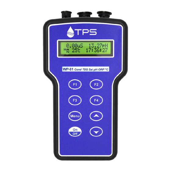
Page 5: Introduction
Page 5 1. Introduction 1.1 WP-81 Display and Controls... - Page 6 (section 7.1), setting the manual temperature compensation (section 7.4), setting the clock (section 15.1), setting the automatic logging period (section 10), and displaying GLP information (section 8.1). key is also used to initialise the WP-81 at turn-on. See section 18. Switches the WP-81 on and off.
-
Page 7: Unpacking Information
Page 7 1.2 Unpacking Information Before using your new WP-81, please check that the following accessories have been included: Part No 1. WP-81 Conductivity-TDS-Sal-pH-ORP-Temp instrument ..121132/1 ....................121132/3 ....................121132/5 2. Conductivity/ATC/Temperature Sensor: 1, 3 or 5m cable k=10... -
Page 8: Specifications
Page 8 1.3 Specifications Conductivity Ranges ......4 ranges, with automatic range selection. k=0.1 Sensor ... 0 uS/cm to 2000 uS/cm k=1.0 Sensor ... 0 uS/cm to 20.00 mS/cm k=10 Sensor ... 0 uS/cm to 200.0.mS/cm Resolution ......0.05% of selected range Accuracy ...... - Page 9 Page 9 General Specifications Temperature Compensation: Conductivity/TDS/Salinity ..Automatic -5 to 70 (only – not for mV/ORP) ..Automatic 0 to 100 Manual 0 to 100 Calibration: pH ........Auto Standard Recognition in pH4.01, pH6.86, pH7.00, pH9.18 or pH10.01 pH Sensor Asymmetry Range -1.00 to +1.00 pH pH Sensor Slope Range ..
- Page 10 Page 10 Battery Saver ......On : Auto switch-off after 5 minutes Off : Continuous use Bar Graph display of battery charge level. Value of battery voltage available for troubleshooting. Good Laboratory Practices ..Date, Time Value last Conductivity, Temperature calibration are stored, and can be recalled or sent to the RS232 port at any time.
-
Page 11: Menu Structure
Page 11 2. WP-81 Menu Structure A detailed breakdown of the menu system of the WP-81 is shown below. This diagram provides a quick reference for the WP-81 menu functions. F1:Cal F1:Cond F2:pH F3:Temp F2:Notepad F1:Recall... -
Page 12: Operating Modes
Page 12 3. Operating Modes 3.1 Selecting Conductivity, TDS (setting factor) or Salinity Mode To select Conductivity, TDS or Salinity mode… F3:Mode)… 1. Select the Mode menu ( F1:Cond/TDS/Sal F3:pH F4:mV 2. Press to select Conductivity mode Menu. F1:Cond. F2:TDS F3:Sal. -
Page 13: Conductivity (Tds/Salinity) Calibration
4.1 Calibration Procedure 1. Plug the Conductivity sensor into the Conductivity socket. If a k=0.1 or k=10 sensor is being used, ensure that the WP-81 is set to the correct k factor before using the instrument (see section 16). 2. Switch the meter on. - Page 14 8. When the reading has stabilised, press the key to calibrate. The “” will now be replaced by a decimal point, if calibration was successful. 9. The WP-81 is now calibrated for Conductivity and is ready for use in this mode.
-
Page 15: Calibration Notes
This information can be recalled or printed later using the GLP function (see section 8). 5. The WP-81 displays the value of the standard to which it will attempt to calibrate. Ensure that the standard value displayed corresponds to the standard that you are using. -
Page 16: Ph Calibration
Page 16 5. pH Calibration 5.1 Calibration Procedure 1. Plug the pH sensor into the pH socket. Temperature measurements are made via the Conductivity sensor, so this needs to be connected for Automatic Temperature Compensation. 2. Switch the meter on. 3. -
Page 17: Calibration Notes
This information can be recalled or printed later using the GLP function (see section 8). 4. The WP-81 displays the value of the pH buffer to which it will attempt to calibrate. Ensure that the buffer value displayed corresponds to the... -
Page 18: Calibration Messages
For example… 1 Point Cal. OK Asy= 0.10pH 2. If a 1-point calibration has failed, the WP-81 will display the following message, and the failed asymmetry value of the sensor. For example… 1 Point Cal. Fail 1 Point Cal. -
Page 19: Temperature Calibration
7.2 Calibration Notes 1. Temperature calibration information is retained in memory when the WP-81 is switched off, even when the battery is removed. This information can be recalled or printed later using the GLP function (see section 8). -
Page 20: Calibration Messages
Page 20 7.3 Calibration Messages 1. If a temperature calibration has been successfully performed, the WP-81 will display the following message and the offset value of the sensor. For example… Calibrate OK Offset= 2. If a temperature calibration has failed, the WP-81 will display the following message, and the failed offset value of the sensor. -
Page 21: Good Laboratory Practices (Glp)
Page 21 8. Good Laboratory Practices (GLP) The WP-81 keeps a record of the date and time of the last Conductivity, pH and Temperature calibrations as part of GLP guidelines. 8.1 To recall GLP information on the display 1. Switch the meter on. -
Page 22: Failed Calibration
Page 22 8.2 Failed Calibration If calibration has failed, the GLP function will reset the date and time to zero. The WP-81 still shows the results of the last successful calibration. For example… Cond Zero 0.00uS k=1.00 @ 00/00/00 00:00 @ 00/00/00 00:00 Asy 0.10pH... -
Page 23: Instrument Serial Number
Page 23 8.4 Instrument Serial Number In case the serial number that is fitted to the rear of the WP-81 is removed or becomes illegible, it is also available on the WP-81 display. The serial number is displayed at turn-on, for example…... -
Page 24: Notepad Function
3. Repeat steps 1 & 2 as often as required. The maximum number of readings that can be stored in the Notepad is 3600. 9.2 Recalling Records from the Notepad To recall records from the Notepad onto the WP-81 display: F2:Notepad) 1. Select the Notepad menu ( 2. -
Page 25: Erasing Records From The Notepad
2. Connect the other end of the RS232 cable to an RS232 Printer, or to COM1 or COM2 of a PC. 3. Ensure that the baud rate for the printer or PC and the WP-81 are the same. If necessary, alter the baud rate of the WP-81 (see section 11.1). -
Page 26: Automatic Data Logging
For example, if the period was set to 05, followed by , then the WP-81 will automatically log a record every 5 seconds. 5. The WP-81 will ask if the records are to be logged into the Notepad, or sent directly to the RS232 port. Press to log records into the Notepad (maximum of 3600 readings). - Page 27 2.76mS 7.00pH Sending 12:00:00 The WP-81 will beep each time a record is sent to the RS232 port. 8. Press to stop automatic logging. Notes: 1. The clock must be set before the WP-81 will allow automatic logging to start.
-
Page 28: Rs232 Port
95 and later is optionally available (part number 130086). Once the data is saved to disk, the next problem is how to use it. The data sent by the WP-81 is formatted in fixed-width columns that can be ® ®... -
Page 29: Commands
Page 29 11.5 Commands The following commands can be sent from a PC to the WP-81. Note that <cr> denotes carriage return and <lf> denotes a line feed. Action Command Notes Request current ?D<cr> Returns the current Conductivity/ data TDS/Salinity, pH, Temperature, date and time from the WP-81. -
Page 30: Data Format
Page 30 11.6 Data Format Data is returned to the RS232 Port by the WP-81 in the following format. Please note that a “ ” shown anywhere in this section denotes one space. LLLLCCCCCCcccPPPPPPpppTTTTTTtttdd/mm/yyhh:mm:ss where… LLLL is the Log Number. Maximum 4 characters, right justified. -
Page 31: Glp Data Format
Page 31 11.7 GLP Data Format GLP information is returned as 8 lines terminated by a carriage return. When using the “?G” command (section 11.5), the computer must respond with a character after receiving each line. For example… WP81 V6.0 S1234 @ 31/12/03 12:00 Conductivity Zero= 0.00uS @ 30/03/11 11:05... -
Page 32: Importing Data Into Microsoft Excel
Page 32 12. Importing Data into Microsoft Excel The following procedure details the method for importing a WP-81 text data file into Microsoft Excel and select File Open Start Microsoft Excel In the “Files of type:” pull-down box, choose “Text Files (*prn; *.txt;... - Page 33 TPS recommends the breaks be inserted. Press “Next >” after the column breaks have been inserted. Simply press “Finish” at step 3 of the Text Import Wizard. TPS recommends that the data format for each column be set once the data is in spreadsheet format.
-
Page 34: Battery Saver Function
Page 34 13. Battery Saver Function The WP-81 is equipped with a battery saver function. If no button has been pressed for five minutes, the unit beeps and flashes the display for 20 seconds, and then shuts off. This function can be switched off for continuous use. -
Page 35: Recharging The Battery
5.60 volts. The battery should be recharged at this point. If the battery is not recharged, the WP-81 will switch itself off when the battery drops below 5.00 volts. To recharge the battery…... -
Page 36: Clock Function
Notes 1. The WP-81 does not test for a valid day of the month when setting the clock (eg: attempting to enter 30/03/11 is not corrected). 2. The WP-81 does test for leap years. -
Page 37: Selecting K=0.1 Or K=10 Conductivity Sensors
The WP-81 automatically recognises a k=1.0 sensor. The WP-81 does not automatically recognise k=0.1 or k=10 sensors. When a k=0.1 or k=10 sensor is used, the WP-81 must be set to the correct k factor before use. The following procedure describes how to select a k=0.1 or k=10 sensor. -
Page 38: Selecting Buffers For Auto Buffer Recognition
Page 38 17. Selecting Buffers for Auto Buffer Recognition The WP-81 is factory set to automatically recognise pH4.01, pH7.00 and pH9.18 buffers. However, some users may prefer to use pH6.86 instead of pH7.00 and pH10.01 instead of pH9.18. The following procedure describes how to set which of these buffers are automatically recognised at calibration. -
Page 39: Initialising The Wp-81
: Con TDS Sal pH MUST ReCalibrate (The “s” after WP-81 is shown when the RS232 serial port option is fitted) 4. The meter then displays Conductivity, pH and Temperature. Note that the decimal points have been replaced with a ““, to indicate that the unit requires re-calibration. -
Page 40: Troubleshooting
Error Message Possible Causes Remedy Factory Cal. The EEPROM chip which The unit must be returned to Failed contains the factory TPS for service. calibration information has failed. Handbook Memory Failed User calibration settings Re-calibrate the instrument. Calibration Lost have been lost or A 2-point calibration will be corrupted. -
Page 41: Conductivity Troubleshooting
Page 41 20.2 Conductivity Troubleshooting Symptom Possible Causes Remedy Unit fails to Calibration settings outside Initialise the unit. See section calibrate, even of allowable limits due to with new sensor. previous failed calibration. Unit attempts Sensor has Zero error. Thoroughly rinse sensor in Span calibration distilled water and allow to instead of Zero... - Page 42 Page 42 Conductivity Troubleshooting, continued... Standard 1. White protective cover is The white protective cover calibration fails, not fitted or upside down. MUST be fitted for correct and k factor is readings. The vent hole must less than 0.075, be towards the cable end of 0.75 or 7.5, the sensor.
-
Page 43: Ph And Mv/Orp Troubleshooting
1. Incorrect primary buffer. Ensure that you are using fails (Slope is less the primary pH buffer for than 85.0%). which the WP-81 has been set (see section 17). 2. Glass bulb not clean. Clean glass bulb as per instructions supplied with the sensor. -
Page 44: Temperature Troubleshooting
Page 44 pH and ORP/mV Troubleshooting, continued... Inaccurate Reference junction blocked. Clean reference junction, as readings, even per instructions supplied with when calibration is the sensor. successful. Displays 7.00 for Electrical short in connector. 1. Check connector. all solutions. Replace if necessary. 2. -
Page 45: Appendices: Ph And Conductivity Sensor Theory
21.1 Care, Cleaning and Maintenance of Conductivity Sensors 21.1.1 Care of Conductivity sensors The conductivity section of the sensor supplied with your WP-81 consists of two platinum wires that are plated with a layer of “platinum-black”. This is quite a soft layer and is required for stable, accurate measurements. In time, the platinum-black layer may wear off in some applications, at which time the sensor will require replatinising (see section 21.2). -
Page 46: Replatinising Conductivity Sensors
21.2 Replatinising Conductivity Sensors There are several ways to replatinise Conductivity sensors. 1. The simplest way is to return the sensor to the TPS factory. We can fully clean the sensor, replatinise it and test all aspects of its performance. -
Page 47: Ph Sensor Fundamentals
Page 47 21.3 pH Sensor Fundamentals A combination pH Sensor is two sensors in one. The sensing membrane is the round or spear shaped bulb at the tip of the sensor. This produces a voltage that changes with the pH of the Solution. This voltage is measured with respect to the second part of the sensor, the reference section. - Page 48 Page 48 21.3.2 The Slope of a pH Sensor As mentioned above, a pH sensor produces 0 mV output at around 7.00 pH. As the pH goes up, an “ideal” pH sensor produces -59mV/pH unit at C As the pH goes down, an ideal pH sensor produces +59mV/pH unit.
- Page 49 Page 49 21.3.3 Temperature Compensation The slope of a pH sensor (section 21.3.2) is affected by temperature. This effect is compensated for either by using an Automatic Temperature Compensation (ATC) sensor or by entering the sample temperature manually. Figure 21-3 shows the slope of a pH sensor at various temperatures.
-
Page 50: Warranty
Please read service details on our ‘Service’ web page first: http://www.tps.com.au/service.htm TPS Pty Ltd has a reputation for prompt and efficient service. If you feel that this equipment is in need of repair, please re-read the manual. Sometimes, instruments are received for "repair" in perfect working order. - Page 51 Page 51 Please check that the following is enclosed with your equipment: A TPS ‘Service / Return Goods Form’ – see web link below: http://www.tps.com.au/Service/Service%20form_web.pdf Your full name Your company name Your email address or fax number ...
Need help?
Do you have a question about the WP-81 and is the answer not in the manual?
Questions and answers