Table of Contents
Advertisement
Congratulations !
You have purchased the latest in Handheld pH-ORP-Temperature
instrumentation. We trust that your new WP-80 will give you many years
of reliable service.
The WP-80 is a breeze to operate. This manual has been designed to
help you get started, and also contains some handy application tips. If at
any stage you require assistance, please contact either your local TPS
representative or the TPS factory in Brisbane.
The manual is divided into the following sections:
1.
Table of Contents
Each major section of the handbook is clearly listed. Sub-sections
have also been included to enable you to find the information you
need at a glance.
2.
Introduction
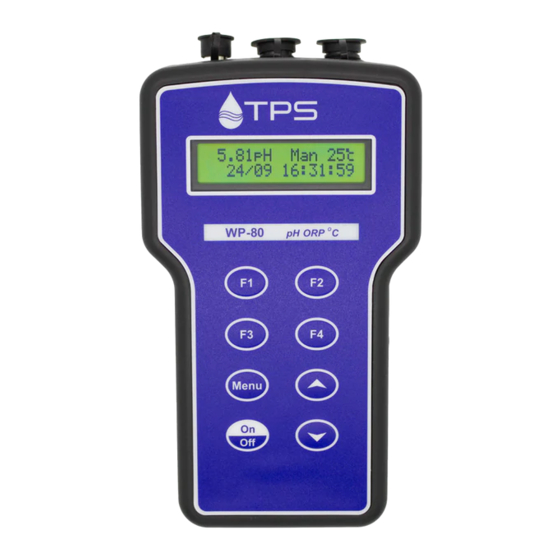
The introduction has a diagram and explanation of the display and
controls of the WP-80. It also contains a full listing of all of the items
that you should have received with your WP-80. Please take the time
to read this section, as it explains some of items that are mentioned
in subsequent sections.
3.
Main Section
The main section of the handbook provides complete details of the
WP-80, including operating modes, calibration, troubleshooting,
specifications, and warranty terms.
4.
Appendices
Appendices containing background information and application notes
are provided at the back of this manual.
Model WP-80
pH, ORP, Temp Meter
Version:
5.2
Date:
1-Jul-2012
Advertisement
Table of Contents
Troubleshooting

Related Manuals for TPS WP-80


Summary of Contents for TPS WP-80
- Page 1 Introduction The introduction has a diagram and explanation of the display and controls of the WP-80. It also contains a full listing of all of the items that you should have received with your WP-80. Please take the time to read this section, as it explains some of items that are mentioned in subsequent sections.
- Page 2 Page 2 TPS Pty Ltd ABN 30 009 773 371 4 Jamberoo Street Springwood, Brisbane, Australia, 4127 Phone : (07) 32 900 400 International : 61 7 32 900 400 : (07) 3808 4871 International : 61 7 3808 4871 Email : tps@tps.com.au...
-
Page 3: Table Of Contents
Page 3 Contents Introduction ..................5 WP-80 Display and Controls ..............5 Unpacking Information ................7 Specifications ..................8 WP-80 Menu Structure ..............10 Operating Modes ................11 Selecting pH, mV/ORP or Relative mV/ORP Mode ......11 pH Calibration ................13 Calibration Procedure ................ - Page 4 Setting the Clock ................34 14.2 Displaying or Hiding the Clock ............34 Selecting Buffers for Auto Buffer Recognition ....... 35 Initialising the WP-80 ..............36 Instrument firmware version number........36 Troubleshooting ................ 37 18.1 General Errors .................. 37 18.2...
-
Page 5: Introduction
Page 5 1. Introduction 1.1 WP-80 Display and Controls... - Page 6 (section 7), setting manual temperature compensation (section 7.4), setting the clock (section 14.1), setting the automatic logging period (section 10), and displaying GLP information (section 8.1). key is also used to initialise the WP-80 at turn-on. See section 16. Switches the WP-80 on and off.
-
Page 7: Unpacking Information
Page 7 1.2 Unpacking Information Before using your new WP-80, please check that the following accessories have been included: Part No 1. WP-80 pH-ORP-Temperature Instrument ......121109/1 ....................121109/3 ....................121109/5 2. pH Sensor: 1, 3 or 5m cable (see cable label for part No) 3. -
Page 8: Specifications
Page 8 1.3 Specifications Range ........0 to 14.00 pH Resolution ......0.01 pH Accuracy ......±0.01 pH mV/ORP Range ........0 to ±500.0 and 0 to ±1500 mV (auto- ranging) Resolution ......0.15 and 1 mV Accuracy ......±0.3 and ±1 mV Temperature Range ........ - Page 9 Page 9 Memory ........3600 readings including date and time. Automatic Logging....User-set for one reading every 1 to 90 seconds, 1 to 90 minutes, or 1 to 24 hours. RS232 Output ......300, 1200, 9600 & 19200 baud. 8 bits, no parity, 1 stop bit, XON/XOFF Protocol.
-
Page 10: Menu Structure
Page 10 2. WP-80 Menu Structure A detailed breakdown of the menu system of the WP-80 is shown below. This diagram provides a quick reference for the menu functions available for the WP-80. → F1:Cal. → F1:pH (available when in pH mode) F2:Temp →... -
Page 11: Operating Modes
Page 11 3. Operating Modes 3.1 Selecting pH, mV/ORP or Relative mV/ORP Mode To select pH, mV/ORP or Relative mV/ORP mode… , then → → → → F3:Mode)… 1. Select the Mode menu ( F1:pH F2:mV/ORP F3:Rel mV/ORP 2. Press to select pH mode. - Page 12 Page 12 3.1.3 Relative mV/ORP Mode Displays Relative mV/ORP and Temperature readings simultaneously. Press to alternatively show absolute mV/ORP or the date and time. For example… 25.0° ° ° ° c 25.0° ° ° ° c 1000mVR 1000mVR 660mV F4:Zeros 31/12 12:00:00 If the temperature sensor is unplugged, no temperature value is displayed…...
-
Page 13: Ph Calibration
Page 13 4. pH Calibration A “∗” in place of the decimal point indicates that the pH readout is not calibrated, or a past calibration has failed. The “∗” will be removed once a full two-point pH calibration has been successfully performed. 4.1 Calibration Procedure 1. - Page 14 14. When the reading has stabilised, press the key to calibrate. The "∗" will now be replaced by a decimal point, if calibration was successful. 15. The WP-80 is calibrated and ready for use in this mode. Discard the used samples of buffer.
-
Page 15: Calibration Notes
This information can be recalled or printed later using the GLP function (see section 8). 4. The WP-80 displays the value of the pH buffer to which it will attempt to calibrate. Ensure that the buffer value displayed corresponds to the buffer that you are using. -
Page 16: Mv/Orp Calibration
Page 16 5. mV/ORP Calibration The mV/ORP section is factory calibrated. There is no sensor calibration using a calibration standard for this mode. 6. Relative mV/ORP Calibration Select Relative mV/ORP mode when measurements relative to a calibration standard are required. Calibration of the Relative mV/ORP mode is simply a matter of zeroing the reading when the sensor is in the known standard. -
Page 17: Notes
25.0° ° ° ° c 0mVR 0mVR 660mV F4:Zeros 31/12 12:00:00 8. The WP-80 Relative mV/ORP mode is now zeroed and is ready for use. The readout can be re-zeroed by pressing the key whenever required. 6.1 Notes 1. The Relative mV/ORP offset is retained in memory when the WP-80 is switched off, even when the battery is removed. -
Page 18: Temperature Calibration
7.2 Calibration Notes 1. Temperature calibration information is retained in memory when the WP-80 is switched off, even when the battery is removed. This information can be recalled later using the GLP function (see section 2. Temperature does not need to be recalibrated unless the... -
Page 19: Calibration Messages
Page 19 7.3 Calibration Messages 1. If a temperature calibration has been successfully performed, the WP-80 will display the following message and the offset value of the sensor. For example: Calibrate OK 1.0° ° ° ° c Offset= 2. If a temperature calibration has failed, the WP-80 will display the following message, and the failed offset value of the sensor. -
Page 20: Good Laboratory Practices (Glp)
Page 20 8. Good Laboratory Practices (GLP) The WP-80 keeps a record of the date and time of the last pH asymmetry, pH slope and Temperature offset calibrations as part of GLP guidelines. 8.1 To recall GLP information on the display 1. -
Page 21: Failed Calibration
Page 21 8.2 Failed Calibration If calibration has failed, the GLP function will reset the date and time to zero. The WP-80 still shows the results of the last successful calibration. For example: Asy 0.10pH Slope 100.0% @ 00/00/00 00:00 @ 00/00/00 00:00 °... -
Page 22: Instrument Serial Number
Page 22 8.4 Instrument Serial Number In case the serial number that is fitted to the rear of the WP-80 is removed or becomes illegible, it is also available on the WP-80 display. • The serial number is displayed at turn-on, for example…... -
Page 23: Notepad Function
3. Repeat steps 1 & 2 as often as required. The maximum number of readings that can be stored in the Notepad is 3600. 9.2 Recalling Records from the Notepad To recall records from the Notepad onto the WP-80 display: → → → → F2:Notepad). 1. Select the Notepad menu ( 2. -
Page 24: Erasing Records From The Notepad
2. Connect the other end of the RS232 cable to an RS232 Printer, or to COM1 or COM2 of a PC. 3. Ensure that the baud rate for the printer or PC and the WP-80 are the same. If necessary, alter the baud rate of the WP-80 (see section 11.1). -
Page 25: Automatic Data Logging
If the period was set to 05, followed by , then the WP-80 will automatically log a record every 5 seconds. 5. The WP-80 will ask if the records are to be logged into the Notepad, or sent directly to the RS232 port. Press to log records into the Notepad (maximum of 3600 readings). - Page 26 Page 26 7. To start automatic logging, press in normal display mode. If the WP-80 is logging into the Notepad, the display will look like this: 25.0° ° ° ° C 7.00pH Log# 1 12:00:00 The log number will increment and the WP-80 will beep each time a reading is recorded.
-
Page 27: Rs232 Port
Press to instantly send readings to the RS232 port whenever the WP-80 is in normal run mode. This function is disabled if the automatic logging period is set to greater than zero (see section 10). Records can be sent directly to the RS232 port rather than stored in memory during automatic data logging. -
Page 28: Commands
Page 28 11.5 Commands The following commands can be sent from a PC to the WP-80. Note that <cr> denotes carriage return and <lf> denotes a line feed. Action Command Notes Request current ?D<cr> Returns the current pH or mV/ORP,... -
Page 29: Data Format
Page 29 11.6 Data Format Data is returned to the RS232 Port by the WP-80 in the following format. A “•” shown anywhere in this section denotes one space. LLLL PPPPPPuuu TTTTTTuuu dd/mm/yy hh:mm:ss is the Log Number. Maximum 4 characters, right LLLL justified. -
Page 30: Importing Data Into Microsoft Excel
Page 30 11.8 Importing Data into Microsoft Excel The following procedure details the method for importing a WP-80 text ® ® data file into Microsoft Excel ® ® and select File → Open Start Microsoft Excel In the “Files of type:” pull-down box, choose “Text Files (*prn; *.txt;... - Page 31 TPS recommends the breaks be inserted. Press “Next >” after the column breaks have been inserted. Simply press “Finish” at step 3 of the Text Import Wizard. TPS recommends that the data format for each column be set once the data is in spreadsheet format.
-
Page 32: Battery Saver Function
Page 32 12. Battery Saver Function The WP-80 is equipped with a battery saver function. If no button has been pressed for five minutes, the unit beeps and flashes the display for 20 seconds, and then shuts off. This function can be switched off for continuous use. -
Page 33: Recharging The Battery
5.60 volts. The battery should be recharged at this point. If the battery is not recharged, the WP-80 will switch itself off when the battery drops below 5.00 volts. To recharge the battery…... -
Page 34: Clock Function
Notes 1. The WP-80 does not test for a valid day of the month when setting the clock (eg: attempting to enter 31/02/11 is not corrected). 2. The WP-80 does test for leap years. -
Page 35: Selecting Buffers For Auto Buffer Recognition
Page 35 15. Selecting Buffers for Auto Buffer Recognition The WP-80 is factory set to automatically recognise pH4.01, pH7.00 and pH9.18 buffers. However, some users may prefer to use pH6.86 instead of pH7.00 and pH10.01 instead of pH9.18. The following procedure describes how to set which of these buffers are automatically recognised at calibration. -
Page 36: Initialising The Wp-80
: pH ORP MUST ReCalibrate (The “s” after WP-80 is shown when the RS232 serial port option is fitted) 4. The meter then displays pH and Temperature. Note that the decimal points have been replaced with a “∗”, to indicate that the unit requires recalibration. -
Page 37: Troubleshooting
Possible Causes Remedy Factory Cal. The EEPROM chip which The unit must be returned to Failed contains the factory TPS for service. • mV/ORP & Temperature calibration information then: has failed. readings may be up to 10% incorrect. • pH readings will be... -
Page 38: Ph And Mv/Orp Troubleshooting
2 Point calibration 1. Incorrect primary buffer. Ensure that you are using the buffers which the WP-80 fails (Slope is less than 85.0%). has been set to automatically recognise (see section 15). 2. Glass bulb not clean. -
Page 39: Temperature Troubleshooting
Page 39 pH and mV/ORP Troubleshooting, continued... Unstable 1. Electrolyte chamber Refill with saturated KCl readings. needs to be refilled. filling solution. 2. Reference junction Clean reference junction, as blocked. per instructions supplied with the sensor. 3. Glass bulb not clean. Clean glass bulb as per instructions supplied with the sensor. -
Page 40: Appendices: Ph Sensor Theory
Page 40 19. Appendices: pH Sensor Theory A combination pH Sensor is two sensors in one. The sensing membrane is the round or spear shaped bulb at the tip of the sensor. This produces a voltage that changes with the pH of the Solution. This voltage is measured with respect to the second part of the sensor, the reference section. -
Page 41: Slope Of A Ph Sensor
Page 41 19.2 Slope of a pH Sensor As mentioned above, a pH sensor produces 0 mV output at around 7.00 pH. As the pH goes up, an “ideal” pH sensor produces -59mV/pH unit at C As the pH goes down, an ideal pH sensor produces +59mV/pH unit. -
Page 42: Ph Temperature Compensation
Page 42 19.3 pH Temperature Compensation The slope of a pH sensor is affected by temperature. This effect is compensated either using Automatic Temperature Compensation (ATC) sensor or by entering the sample temperature manually. Figure 19-3 shows the slope of a pH sensor at various temperatures. -
Page 43: Warranty
Please read service details on our ‘Service’ web page first: http://www.tps.com.au/service.htm TPS Pty Ltd has a reputation for prompt and efficient service. If you feel that this equipment is in need of repair, please re-read the manual. Sometimes, instruments are received for "repair" in perfect working order. - Page 44 Page 44 Please check that the following is enclosed with your equipment: • A TPS ‘Service / Return Goods Form’ – see web link below: http://www.tps.com.au/Service/Service%20form_web.pdf • Your full name • Your company name • Your email address or fax number •...
Need help?
Do you have a question about the WP-80 and is the answer not in the manual?
Questions and answers