Table of Contents
Advertisement
Congratulations !
You have purchased the latest in Handheld Conductivity-Salinity-Temperature
instrumentation. We trust that your new WP-84 will give you many years of
reliable service.
The WP-84 is a breeze to operate. This manual has been designed to help you
get started, and also contains some handy application tips. If at any stage you
require assistance, please contact either your local TPS representative or the
TPS factory in Brisbane.
The manual is divided into the following sections:
1. Table of Contents
Each major section of the handbook is clearly listed. Sub-sections have also
been included to enable you to find the information you need at a glance.
2. Introduction
The introduction has a diagram and explanation of the display and controls of
the WP-84. It also contains a full listing of all of the items that you should
have received with your WP-84. Please take the time to read this section, as
it explains some of items that are mentioned in subsequent sections.
3. Main Section
The main section of the handbook provides complete details of the WP-84,
including operating modes, calibration, troubleshooting, specifications, and
warranty terms.
4. Appendices
Appendices containing background information and application notes are
provided at the back of this manual.
TPS Pty Ltd
4 Jamberoo Street
Springwood, Brisbane,
Australia, 4127
Phone
: (07) 32 900 400
International
: 61 7 32 900 400
Fax
: (07) 3808 4871
International
: 61 7 3808 4871
tps@tps.com.au
E-mail
:
Web
: www.tps.com.au
Model WP-84
Conductivity-Salinity-
Temp. Meter
Handbook Version : 2.0
Date
: 05
Mar 01
Author
: MS
Advertisement
Table of Contents
Troubleshooting

Related Manuals for TPS WP-84


Summary of Contents for TPS WP-84
- Page 1 The introduction has a diagram and explanation of the display and controls of the WP-84. It also contains a full listing of all of the items that you should have received with your WP-84. Please take the time to read this section, as it explains some of items that are mentioned in subsequent sections.
-
Page 2: Table Of Contents
Page 2 Contents Introduction..................4 1.1 WP-84 Display and Controls................4 1.2 Unpacking Information..................6 1.3 Specifications....................7 WP-84 Menu Structure ..............9 Conductivity Mode................ 10 3.1 Selecting Conductivity Mode ................10 3.2 Conductivity Calibration ................. 11 3.3 Calibration Notes .................... 12 3.4 Calibration Messages .................. - Page 3 Clock Function ................32 12.1 Setting the Clock ..................32 12.2 Displaying or Hiding the Clock..............32 Selecting k=0.1 or k=10 Sensors ..........33 Initialising the WP-84 ..............34 Instrument firmware version number........34 Troubleshooting................ 35 16.1 General Errors .................... 35 16.2 Conductivity and Salinity Troubleshooting..........
-
Page 4: Introduction
Page 4 1. Introduction 1.1 WP-84 Display and Controls... - Page 5 (optional). See section 10.2. ¯ Only used within the menu system on the WP-84. ° Press to access the user-friendly menu system which makes the WP-84 a breeze to operate. ± ³ keys are used when calibrating temperature readout (section 5), setting the clock (section 12.1), setting the automatic logging period (section 9),...
-
Page 6: Unpacking Information
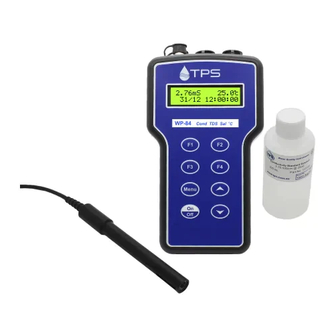
Page 6 1.2 Unpacking Information Before using your new WP-84, please check that the following accessories have been included… Part No 1. WP-84 Conductivity-Salinity-Temperature Instrument......122159 2. k=1/ATC/Temperature Sensor, Plastic body, 1m cable ......122201 3. 2.76mS/cm Conductivity Standard, 200mL...........122306 4. 2 ppK Salinity Standard, 200mL ............122307 5. -
Page 7: Specifications
Page 7 1.3 Specifications Ranges Resolution Accuracy 0 to 2.000 uS/cm 0.001 uS/cm ± Conductivity k=0.1 0.5% of full 0 to 20.00 uS/cm 0.01 uS/cm scale of 0 to 200.0 uS/cm uS/cm selected range 0 to 2000 uS/cm uS/cm at 25 0 to 20.00 mS/cm 0.01 mS/cm... - Page 8 Page 8 General Specifications Temperature Compensation : Automatic, 0 to 100 Cond. Sensor Span Range : k=0.1 Sensor : k=0.075 to k=0.133 k=1.0 Sensor : k=0.75 to k=1.33 k=10 Sensor : k=7.5 to k=13.3 Temp. Sensor Offset Range : -10.0 C to +10.0 Auto Standard Recognition : Cond.
-
Page 9: Menu Structure
Page 9 2. WP-84 Menu Structure A detailed breakdown of the menu system of the WP-84 is shown below. This diagram provides a quick reference for the menu functions available for the WP-84. → F1:Cal. → F1:Conductivityl F1:Salinity F3:Temp F4:ATC % →... -
Page 10: Conductivity Mode
3.1 Selecting Conductivity Mode To select Conductivity readout mode… → → F3:Mode). 1. Select the Mode menu ( 2. Select F1:Conductivity from the menu. 3. The WP-84 resumes normal operation in Conductivity mode. For example… 2.76mS 25.0 31/12 12:00:00 Press... -
Page 11: Conductivity Calibration
3.2 Conductivity Calibration 1. Plug the Conductivity/Salinity sensor into the Sensor socket. If a k=0.1 or k=10 sensor is being used, ensure that the WP-84 is set to the correct k factor before using the instrument (see section 13). 2. Select Conductivity Mode, as per section 3.1. -
Page 12: Calibration Notes
This information can be recalled or printed later using the GLP function (see section 7). 5. The WP-84 displays the value of the standard to which it will attempt to calibrate. Ensure that the standard value displayed corresponds to the standard that you are using. -
Page 13: Salinity Mode
4.1 Selecting Salinity Mode To select Salinity readout mode… → → F3:Mode). 1. Select the Mode menu ( 2. Select F3:Salinity from the menu. 3. The WP-84 resumes normal operation in Salinity mode. For example… 2.00ppK 25.0 31/12 12:00:00 Press... -
Page 14: Conductivity Calibration
4.2 Salinity Calibration 1. Plug the Conductivity/Salinity sensor into the Sensor socket. If a k=0.1 or k=10 sensor is being used, ensure that the WP-84 is set to the correct k factor before using the instrument (see section 13). 2. Select Salinity Mode, as per section 4.1. -
Page 15: Calibration Notes
This information can be recalled or printed later using the GLP function (see section 7). 5. The WP-84 displays the value of the standard to which it will attempt to calibrate. Ensure that the standard value displayed corresponds to the standard that you are using. -
Page 16: Temperature Calibration
1. If a temperature calibration has been successfully performed, the WP-84 will display the following message and the offset value of the sensor. Calibrate OK Offset= 2. If a temperature calibration has failed, the WP-84 will display the following message and the failed offset value of the sensor. Calibrate Failed... - Page 17 Page 17 Offset= 10.5...
-
Page 18: Atc Coefficient
The temperature of the solution. It is therefore impossible to set a single ATC Coefficient in the factor which will be correct for all solutions which the WP-84 will be used to test. The ATC Coefficient is set to 2.0 %/ C in the factory. -
Page 19: Calculating The Atc Coefficient Of A Solution
Page 19 6.2 Calculating the ATC Coefficient of a Solution Set the ATC Coefficient to zero using the procedure detailed in section 6.1. Ensure that the temperature function has been calibrated (see section 5.1). The conductivity function does not need to be calibrated at this point. Warm or cool the solution to approximately 5 C below the temperature at which you expect to take sample measurements. -
Page 20: Good Laboratory Practices (Glp)
Page 20 7. Good Laboratory Practices (GLP) The WP-84 keeps a record of the date and time of the last Conductivity, Salinity and Temperature calibrations as part of GLP guidelines. The span values for Conductivity and Salinity are stored separately. -
Page 21: Failed Calibration
Exit 7.2 Failed Calibration If calibration has failed, the GLP function will reset the date and time to zero. The WP-84 still shows the results of the last successful calibration. For example… Cond Zero 0.00uS k=1.00 @ 2.76mS @ 00/00/00 00:00... -
Page 22: Printing Glp Information To The Rs232 Port
ENDS 7.4 Instrument Serial Number In case the serial number that is fitted to the rear of the WP-84 is removed or becomes illegible, it is also available on the WP-84 display. • The serial number is displayed at turn-on, for example…... -
Page 23: Notepad Function
To erase all records from the Notepad: → F2:Notepad). 1. Select the Notepad menu ( 2. Select F2:Erase from the menu 3. The WP-84 now asks if you are sure that you wish to erase all records… Erase, You Sure? F1:Yes F2:No Press to erase all records from the Notepad. -
Page 24: Printing Records From The Notepad To The Rs232 Port
RS232 port. Windows 95, 98 & ME are shipped with Hyper Terminal, which is suitable for this purpose. 3. Ensure that the baud rate for the printer or PC and the WP-84 are the same. If necessary, alter the baud rate of the WP-84 (see section 10.1). -
Page 25: Automatic Datalogging
, then the WP-84 will automatically log a record every 5 seconds. 5. If the optional RS232 port is fitted, the WP-84 will ask if the records are to be logged into the Notepad, or sent directly to the RS232 port. - Page 26 The WP-84 will beep each time a record is sent to the RS232 port. 8. Press to stop automatic logging. Note The clock must be set before the WP-84 will allow automatic logging to start. The message “Clock Not Set” is displayed if the clock is not set.
-
Page 27: Rs232 Port
10.2 Sending Readings to the RS232 Port Press to instantly send readings to the RS232 port whenever the WP-84 is in normal display mode. This function is disabled if the automatic logging period is set to greater than zero (see section 9). -
Page 28: Commands
Page 28 10.5 Commands The following commands can be sent from a PC to the WP-84. Note that <cr> denotes carriage return and <lf> denotes a line feed. Action Command Notes Request current data ?D<cr> Returns current Conductivity/ Salinity, Temperature, date and time from the WP-84. -
Page 29: Data Format
When requested by a PC with the ?D or ?R commands (section 10.5), each line of data is terminated with a carriage return. When the data is sent by the WP-84 using the Print function (section 8.4) or Send function (section 10.2), each line of data ends with a carriage return and a line... -
Page 30: Glp Data Format
Page 30 10.7 GLP Data Format GLP information is returned as 6 lines terminated by a carriage return. The computer must respond with a character after receiving each line. For example… WP84 V2.0 S1234 @ 31/12/01 13:00 Conductivity Zero= 0.00uS @ 31/12/01 12:00 Conductivity k= 1.00 @ 2.76mS... -
Page 31: Battery Saver Function
Page 31 11. Battery Saver Function The WP-84 is equipped with a battery saver function. If no button has been pressed for five minutes, the unit beeps and flashes the display for 20 seconds, and then shuts off. This function can be switched off for continuous use. -
Page 32: Clock Function
Notes 1. The WP-84 does not test for a valid day of the month when setting the clock (eg: attempting to enter 31/02/01 is not corrected). 2. The WP-84 does test for leap years. -
Page 33: Selecting K=0.1 Or K=10 Sensors
The WP-84 automatically recognises a k=1.0 sensor. The WP-84 does not automatically recognise k=0.1 or k=10 sensors. When a k=0.1 or k=10 sensor is used, the WP-84 must be set to the correct k factor before use. The following procedure describes how to select a k=0.1 or k=10 sensor. -
Page 34: Initialising The Wp-84
“ ∗ ∗ ” to indicate that the unit requires re- calibration. Note When the WP-84 is initialised, the manual k factor selection is re-set to k=10. See section 13 if you wish to select a k=0.1 sensor. 15. Instrument firmware version number. -
Page 35: Troubleshooting
Remedy Factory Cal. The EEPROM chip which The unit must be returned to Failed contains the factory TPS for service. • Conductivity and Salinity calibration information has then… failed. readings will be accurate only if used in same range in which it was calibrated. -
Page 36: Conductivity And Salinity Troubleshooting
Page 36 16.2 Conductivity and Salinity Troubleshooting Symptom Possible Causes Remedy Unit fails to Calibration settings outside of Initialise the unit. See section calibrate, even with allowable limits due to new sensor. previous failed calibration. Unit attempts Span Sensor has Zero error. Thoroughly rinse sensor in calibration instead distilled water and allow to... - Page 37 Page 37 Conductivity and Salinity Troubleshooting, continued... Standard calibration 1. White protective cover is The white protective cover fails, and k factor not fitted or upside down. MUST be fitted for correct is less than 0.075, readings. The vent hole must 0.75 or 7.5, be towards the cable end of the (depending on k...
-
Page 38: Temperature Troubleshooting
Page 38 16.3 Temperature Troubleshooting Symptom Possible Causes Remedy Displays “OVR C” 1. Faulty sensor. Fit new sensor. when sensor is 2. Faulty instrument. Return to factory for repair. plugged in. Temperature 1. Faulty connector. Check the connector and inaccurate and replace if necessary. -
Page 39: Warranty
TPS Pty. Ltd. has a fine reputation for prompt and efficient service. In just a few days, our factory service engineers and technicians will examine and repair your equipment to your full satisfaction. - Page 40 Page 40 Please check that the following is enclosed with your equipment… • Your Name and daytime phone number. • Your company name, ORDER number, and return street address. • A description of the fault. (Please be SPECIFIC.) (Note: "Please Repair" does NOT describe a fault.) Your equipment will be repaired and returned to you by air express where possible.
-
Page 41: Appendices
18.1 Care, Cleaning and Maintenance of Conductivity Sensors 18.1.1 Care of Conductivity sensors The conductivity section of the sensor supplied with your WP-84 consists of two platinum wires that are plated with a layer of “platinum-black”. This is quite a soft layer and is required for stable, accurate measurements. -
Page 42: Replatinising Conductivity Sensors
18.2 Replatinising Conductivity Sensors There are several ways to replatinise Conductivity sensors. 1. The simplest way is to return the sensor to the TPS factory. We can fully clean the sensor, replatinise it and test all aspects of its performance.
Need help?
Do you have a question about the WP-84 and is the answer not in the manual?
Questions and answers