Table of Contents
Advertisement
Quick Links
g
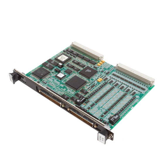
Auxiliary Drive to ISBus Interface Board
Safety Symbol Legend
Indicates a procedure or
condition that, if not strictly
observed, could result in
personal injury or death.
Indicates a procedure or
condition that, if not strictly
observed, could result in damage
to or destruction of equipment.
Note Indicates an essential or
important procedure or
statement.
Innovation Series is a trademark of General Electric Company, USA
IS200ADIIH_A_ _
These instructions do not purport to cover all details or variations in equipment, nor to
provide every possible contingency to be met during installation, operation, and
maintenance. If further information is desired or if particular problems arise that are not
covered sufficiently for the purchaser's purpose, the matter should be referred to GE
Industrial Systems.
This document contains proprietary information of General Electric Company, USA, and is
furnished to its customer solely to assist that customer in the installation, testing,
operation, and/or maintenance of the equipment described. This document shall not be
reproduced in whole or in part, nor shall its contents be disclosed to any third party
without the written approval of GE Industrial Systems.
Section
Functional Description............................................................................................ 2
ISBus ............................................................................................................... 3
Connections ................................................................................................ 3
Performance ................................................................................................ 4
Data Mapping.............................................................................................. 5
Drive Parameters ............................................................................................. 7
LAN Validation .......................................................................................... 7
LAN Faults ................................................................................................. 8
Application Data ..................................................................................................... 9
LED Indicators............................................................................................... 11
Testpoints....................................................................................................... 12
Connectors ..................................................................................................... 12
Installation and Renewal/Warranty Replacement ................................................. 14
How to Order a Board.................................................................................... 14
Board Identification .................................................................................. 14
Warranty Terms ........................................................................................ 15
Placing the Order ...................................................................................... 15
Handling Precautions..................................................................................... 15
New Installations ........................................................................................... 16
ADII Required Parts ................................................................................. 16
Installation Procedures.............................................................................. 17
Replacement Procedures................................................................................ 18
GEI-100305
GE Industrial Systems
Page
Advertisement
Table of Contents

Related Manuals for GE IS200ADIIH A Series


Summary of Contents for GE IS200ADIIH A Series
-
Page 1: Table Of Contents
If further information is desired or if particular problems arise that are not covered sufficiently for the purchaser’s purpose, the matter should be referred to GE Industrial Systems. -
Page 2: Functional Description
The integers must be scaled to the AcDc2000 units (given in the signal map definition). Configuration of the interface is done with either the local keypad on the LDCC board (see Figure 1) or the GE Control System Toolbox (toolbox). Refer to the section, Data Mapping. -
Page 3: Isbus
ISBus The ISBus has one controller (drop 0) and no more then 31 nodes (1-31). The master sends out a stream of bytes containing each ISBus node's references. As the nodes receive the stream of bytes, they pass the stream on to the next node substituting their own feedback data in place of their reference data in the stream. -
Page 4: Performance
Performance On the ISBus, the controller sends control bits and references for each drive in a single stream of bytes. The first drive wired to the controller receives the stream of bytes, retrieves its command bits and references, and passes the stream of bytes onto the next drive substituting its feedback bits and variables for the command bits and references. -
Page 5: Data Mapping
Data Mapping The drive is configured through its keypad or by the toolbox. Once configured, the drive exchanges a fixed set of integer variables with the controller during each ISBus scan. • Variables sent to the drive are defined as references •... - Page 6 Table 4. Boolean Signals Request Bits Innovation AcDc2000 Feedback Bits Innovation Innovation Innovation Series Series AcDc2000 Series Series Mnemonic Mnemonic bit # bit # Heartbeat ref, lan LAN_HTBT_REF AUXCMD00 AUXFB00 LAN_HTBT_FBK Heartbeat fbk, lan Fault reset req, lan LAN_FLT_RST SOFTRES NOFAULT NO_FLT No faults active...
-
Page 7: Drive Parameters
Table 5. AcDc2000 References and Feedback Values (1pu) Variable AcDc2000 Signal (1pu) Armature Current Refr LOADADJ 5000 Speed Refr MMSETP 20000 Ramp Refr 20000 Droop Gain R 10000 Field Flux Refr 5000 Speed Rate Reg Output 5000 Voltage Fdbk ... -
Page 8: Lan Faults
The LAN watchdog function is made up of three parts: • First, the LAN Control Processor (LCP) monitors the ISBus controller’s fault bits and displays an ADII fault, if the ISBus controller is in a fault state. • Second, the LCP monitors it’s own communication with the ISBus controller and if for any reason the ISBus controller is not communicating to LCP, then a drive fault FLT.xxx ADIIRTM displays. -
Page 9: Application Data
Table 6. Fault Codes for ADII Board and ISBus Interface Fault Fault Name Description Corrective Action to Take FLT_LINK_LOS The ISBus controller is not receiving Check to make sure there is a master data from the ISBus LAN. controller on the ISBus and that it is (May be set up to communicating. - Page 10 CHASSIS DCOM ISBus Cable Strain Reliefs IS200ADIIH1A COM1 LNPL Figure 2. ADII Board Layout Diagram • • • • Auxiliary Drive to ISBus Interface Board IS200ADII GEI-100305...
-
Page 11: Led Indicators
LED Indicators The LEDs on the ADII board are only intended for diagnostic purposes. See Table 7 for a description of the LED indications. The drive’s display will show any ISBus faults or ADII board interface faults. Note Debug LEDs DBG1A (DS3) and DBG1B (DS4) are for manufacturing test only. -
Page 12: Testpoints
Testpoints There are seven testpoints on the ADII board as follows: Table 9. Testpoint Descriptions Testpoint Nomenclature Description Positive 5 V dc DCOM Digital common Positive 24 V dc DBG1A Manufacturing use only DBG1B Manufacturing use only 0BACTIVE1 Manufacturing use only 0ONLN1 Manufacturing use only Connectors... - Page 13 Table 12. Connector LNPL, I/O Between the LDCC Board and ADII Board Pin No. Nomenclature Description 1, 2 DCOM Digital common ground 3 − 10 LND0 − LND7 ADII board data signals (D0 − D7) DCOM Digital common ground LNRST Reset signal going to ADII board LNINT ADII board interrupt...
-
Page 14: Installation And Renewal/Warranty Replacement
If the part is under warranty • How to place the order This information helps ensure that GE can process the order accurately and as soon as possible. Board Identification A printed wiring board is identified by an alphanumeric part (catalog) number located near its edge. -
Page 15: Warranty Terms
Warranty Terms The GE Terms and Conditions brochure details product warranty information, including warranty period and parts and service coverage. The brochure is included with customer documentation. It may be obtained separately from the nearest GE Sales Office or authorized GE Sales Representative. -
Page 16: New Installations
When installing an ADII board in a drive that has not had this board in it previously, GE kit number 277A8496G01 is required. This kit includes the ADII board, LNPL cable, DCOM wire, and chassis wire (see Table 15 for individual part numbers). -
Page 17: Installation Procedures
Installation Procedures To prevent electric shock, turn off power to the drive, then test to verify that no power exists in the drive before touching it or any connected circuits. To prevent equipment damage, do not remove, insert, or adjust board connections while power is applied to the equipment. -
Page 18: Replacement Procedures
Care must be taken to keep the ISBus cables away from any high voltage wires and any electrically noisy wires. Keep the cables tight to the ADII board carrier and use the tie down strap holders to hold the cables close to the ADII board and away from the power supply board. - Page 19 Ø Ø Ø Ø To install the new (replacement) board on the board carrier Orient the new board in the same position as the one removed, and seat the board by firmly pressing the board onto the four tabs (on left side) of the back of the front board carrier.
- Page 20 Notes GE Industrial Systems General Electric Company Issue date: 2000-04-05 1999 by General Electric Company, USA. 1501 Roanoke Blvd. All rights reserved. Salem, VA 24153-6492 USA • • • • Auxiliary Drive to ISBus Interface Board IS200ADII...
Need help?
Do you have a question about the IS200ADIIH A Series and is the answer not in the manual?
Questions and answers