Table of Contents
Advertisement
Quick Links
Advertisement
Table of Contents

Related Manuals for GE IC754VBI12CTD


Summary of Contents for GE IC754VBI12CTD
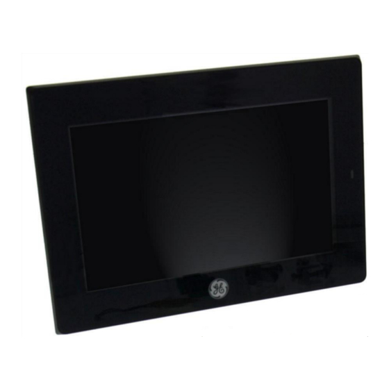
- Page 1 This Datasheet is for the IC754VBI12CTD The IC754VBI12CTD for the GE QuickPanel has 12" TFT touchscreen http://www.qualitrol.com/shop/p-16514-ic754vbi12ctd.aspx For further information, please contact Qualitrol Technical Support at 1-800-784-9385 support@qualitrol.com...
-
Page 2: Table Of Contents
Contents Chapter 1. Introduction ......................... 4 1.1 Specifications............................4 1.1.1 General Specifications ........................4 1.1.2 Physical Specifications and Mounting ....................6 1.1.3 Environmental Specifications ......................6 1.2 QuickPanel+ Hardware User Features ....................7 1.2.1 Overview ............................7 1.2.2 Status Indicators ..........................8 Chapter 2. - Page 3 Contents 4.6.5 Audio (LINE OUT) Details ....................30 4.6.6 Audio (MIC IN) Details ...................... 30 4.6.7 SD Card Slot ........................31 Chapter 5. Detailed Operation ................... 32 Touch Screen Display ......................... 32 5.1.1 Adjusting the Display Brightness ..................32 5.1.2 Configuring the Backlight ....................
-
Page 4: Chapter 1. Introduction
QuickPanel+ User’s Manual–November 2013 GFK-2847 Chapter 1 Introduction Chapter 1. Introduction The QuickPanel+ operator interface is an all-in-one microcomputer designed for maximum flexibility. The design, based on an advanced ARM core microprocessor, brings together a high-resolution touch-screen operator interface with a variety of communications options. You can connect to most industrial equipment through the QuickPanel+ communications ports. -
Page 6: Physical Specifications And Mounting
Chapter 1. Introduction Physical Specifications and Mounting 1.1.2 192 mm × 137 mm × 36 mm Dimensions (L×W×D) (7.56 in. × 5.39 in. × 1.42 in.) Weight 0.800 kg (1.76 lbs) Panel cutout 183.5 mm ×128.5 mm dimensions (7.22 in. × 5.06 in.) Mounting options VESA mount VESA Mount: 75 mm x 75 mm... -
Page 7: Quickpanel+ Hardware User Features
QuickPanel+ User’s Manual–November 2013 GFK-2847 Chapter 1 Introduction 1.2 QuickPanel+ Hardware User Features In addition to the primary touch screen interface, the QuickPanel+ supports a variety of communication ports. The following diagrams show the physical layout of the QuickPanel+ including locations of status LEDs, communications ports, and connectors. -
Page 8: Status Indicators
Status Indicators 1.2.2 The QuickPanel+ operator interface has a tri-color LED that provides visual status indications and an on-board buzzer for audio indications. 1.2.2.1 QuickPanel+ Status LED Operation LED State QuickPanel+ State Amber, steady Operating system starting Green, steady Normal operating state Green, blinking Backlight off Red, blinking... -
Page 9: Chapter 2. Getting Started
Before you attempt to power up the operator interface for the first time, inspect the unit for loose or damaged components. If damage is found (for example, in the form of bent component leads or loose components), contact GE Intelligent Platforms for additional instructions. - Page 10 Chapter 2. Getting Started Serial Port Connector, one Power Connector, one QuickPanel+ User’s Manual–November 2013 GFK-2847...
-
Page 11: Basic Setup
Chapter 2. Getting Started Gasket, one (not shown, pre-installed) Figure 2. QuickPanel+ Package Contents 2.2 Basic Setup Your QuickPanel+ is shipped ready for use after a few configuration steps. To power up, all you need to do is connect a DC power supply using the supplied quick-connect plug. Depending on your application, you may also want to connect and configure optional input devices, communications ports and expansion adapters. -
Page 12: Connecting Input Power
Chapter 2. Getting Started A 24VDC power supply. For requirements, see the Input power specification on page A power terminal block is supplied. 30 – 14 AWG (0.05 – 2.00 mm Power cord ) wires with USB-compatible keyboard (optional) ... -
Page 13: Initial Configuration
Chapter 2. Getting Started Initial Configuration 2.3.2 When you first start up the QuickPanel+, a few configuration steps are necessary. 1. Tap Start , point to Settings and then tap Control Panel. 2. In the Control Panel, double-tap Date and Time to configure the system clock. 3. - Page 14 Chapter 2. Getting Started retained in battery-backed SRAM. Some operating system settings are retained only with user intervention. We recommend the following procedure to shut down the QuickPanel+. shut down the QuickPanel+ 1. Quit any programs that are running and wait for all file operations to complete. 2.
-
Page 15: Chapter 3. Quickpanel+ Software
Chapter 3 QuickPanel+ Software Chapter 3. QuickPanel+ Software This chapter provides introductory information on the QuickPanel+ software with procedures for completing some of the most common tasks you will encounter. 3.1 Operating System Microsoft Windows Embedded Compact 7 is the operating system for the QuickPanel+. It is a full 32-bit O/S with a graphical user interface. -
Page 16: Copy Project To Sd Card
3.4 Copy Project to SD Card This is a custom utility for transferring Proficy Machine Edition View and Control projects between compatible QuickPanel+ units via SD cards. Caution Ensure that the copy or update operation is complete (i.e., no busy or wait cursor displays) b efore disconnecting power. To copy a Machine Edition project to SD card 1. -
Page 17: Ftp Server
3.6 FTP Server The FTP Server included with the QuickPanel+ supports standard (RFC 959). It does not support SFTP or implicit FTPS, which uses different ports and is based on SSH rather than SSL. The configuration of the FTP server is accomplished with the Quick Panel+ Setup Tool. By default, the server is not enabled. - Page 18 Note: If the server status is changed, the QuickPanel+ must be re-booted before changes take effect. QuickPanel+ User’s Manual–November 2013 GFK-2847...
-
Page 19: Chapter 4. Installation
Chapter 4. Installation Chapter 4. Installation This chapter provides the following procedures for installing the QuickPanel+ unit: ■ Installing the Protective Sheet ■ Choosing a Mounting Location ■ Panel Mounting ■ Mounting on a VESA Arm ■ Installing/Replacing the Battery ■... - Page 20 Chapter 4. Installation Figure 5. Mounting Holes Installation Notes: ■ To avoid gasket degradation, limit repeated insertions or removals of the unit and retightening of the mounting clips. For full protection, always use a fresh gasket. Replacement gaskets can be ordered using the part number listed in Appendix B. ■...
-
Page 21: Mounting On A Vesa Arm
Chapter 4. Installation 3. Verify that the gasket is in the bezel channel located on the sides of the QuickPanel+. 4. Insert the hook of the mounting bracket into the mounting hole as shown below. 5. Tighten the screws on the mounting bracket in the clock-wise direction. Note: The torque range for the mounting clamp screws is (0.3 Nm). - Page 22 Chapter 4. Installation QuickPanel+ User’s Manual–November 2013 GFK-2847...
-
Page 23: Installing/Replacing The Battery
Chapter 4. Installation Installing/Replacing the Battery 1. Remove the battery cover by pressing down while sliding outward. 2. Connect the harness connector of the battery to the header, noting keyed orientation. 3. Pull Make sure that positive (red) is down and negative (black) is up 4. - Page 24 Chapter 4. Installation Batteries may present a risk of fire, explosion, or chemical burn if mistreated. Do not crush, disassemble, short-circuit, or dispose of in fire. Use of batteries not specified for use with the QuickPanel+ product may present a risk of fire or explosion. Lithium Battery Warning Do not recharge, disassemble, heat or incinerate lithium batteries.
-
Page 25: Connectors
Chapter 4. Installation 4.6 Connectors Power Connector Pin-out 4.6.1 Interface: 24VDC IN Connector: Terminal Euro (Tyco Electronics 284539-3 or equivalent) Mating Connector: (Tyco Electronics 284510-3 or equivalent) To connect the power supply, refer to 2.3.1 “Connecting Input Power.” Ethernet 4.6.2 The QuickPanel+ is equipped with one 10BaseT/100-BaseTX Ethernet port. -
Page 26: Serial Port
Chapter 4. Installation ■ DHCP (Dynamic Host Configuration Protocol). The network server assigns an IP address while the QuickPanel+ is initializing. (You must be connected to the network).There must be a DHCP server on the connected network for a valid IP address to be assigned. -
Page 27: Audio (Line Out) Details
Chapter 4. Installation 4.6.4.2 USB Device Port Details The USB device port allows the QuickPanel+ operator interface to be used as slave device. Interface: USB2.0 Number of Ports: One Connector: Type-B Mini connector Signal Pin-out Number Name Audio (LINE OUT) Details 4.6.5 Interface: LINE OUT (stereo) Connector: φ3.5 mm Jack... -
Page 28: Sd Card Slot
Chapter 4. Installation Signal Pin-out Number Name Maximum input level: 250mVrms SD Card Slot 4.6.7 The QuickPanel+ is equipped with one standard SD Card port. SD/SDHC memory cards are supported. The SD card slot is spring loaded for easy insertion and removal. 4.6.7.1 Storage Details Connectors: SD card slot (push in - push out method) Card support: SD / SDHC memory card... -
Page 29: Chapter 5. Detailed Operation
Chapter 5 Detailed Operation Chapter 5. Detailed Operation 5.1 Touch Screen Display The QuickPanel+ features a 7” LED Backlit LCD touchscreen display with two-point touch. The touch technology is based on projected capacitance. This allows tracking of the finger without pressured contact conducive to smooth scrolling and multi-touch gesturing capability. Display brightness and backlight operation can be set using the operating system Control Panel. -
Page 30: Calibrating The Touch Screen
Calibrating the Touch Screen 5.1.3 The touchscreen on the QuickPanel+ comes out of the box pre-calibrated but may need to be recalibrated if there are any issues with touch screen responsiveness. 1. Go to the QuickPanel+ Setup tool. 2. Click on the TouchPanel tab. 3. -
Page 31: Mouse
To show/hide the Soft Input Panel On the system tray of the task bar, tap on the icon. The Soft Input Panel can be hidden by selecting ‘Hide Input Panel’. Note: When the SIP is visible, it can be dragged around the screen by its title bar to reveal different parts of the screen that would be obstructed from view by the SIP. - Page 32 2. On the Memory tab, drag the slider to divide into Storage and Program memory. The amount of memory allocated to and used by each area is shown in the dialog box. The blue bar indicates the current amount of unallocated SDRAM and determines the boundaries within which the slider can move.
-
Page 33: Appendix A Product Certifications & Installation Guidelines For Conformance
Low Voltage Directive Self-Declaration in accordance with European Safety for Industrial European Directives; Refer to Control Equipment Declaration of Conformity found at http://www.ge-ip.com/ for a complete list of approved products Electromagnetic Compatibility Self-Declaration in accordance with Directive European Directives; Refer to... -
Page 34: Appendix B Orderable Part Numbers
Changes or modifications to this unit that are not expressly approved by GE Intelligent Platforms could void the user’s authority to operate the equipment. Industry Canada requires the following note to be published: Note: This Class A digital apparatus complies with Canadian CAN ICES-3 (A)/NMB-3(A). - Page 36 Index FCC notice, 36 FTP server, 20 Government regulations, Accesso ries HTTP server, 20 part Industry Canada, 36 numbe Installation, 9, 21 battery, rs, 37 25 guidelines for Agency approvals, 36 conformance, 36 Audio mounting location, 21 panel mounting, 22 protective sheet, 21 VESA arm, 24 Keyboard...
- Page 37 QuickPanel+ User’s Manual–November 2013 GE Intelligent Platforms Additional Resources Information Centers For more information, please visit the GE Headquarters: Intelligent Platforms web site: www.ge-ip.com 1-800-433-2682 or 1-434-978-5100 Global regional phone numbers are available on our web site www.ge-ip.com...
- Page 38 ©2013 GE Intelligent Platforms, Inc. All Rights Reserved *Trademark of GE Intelligent Platforms, Inc. All other brands or names are property of their respective holders. GFK-2847...
Need help?
Do you have a question about the IC754VBI12CTD and is the answer not in the manual?
Questions and answers