Table of Contents
Advertisement
Advertisement
Table of Contents

Related Manuals for Jung IPS 100 REG


Summary of Contents for Jung IPS 100 REG
- Page 1 Product documentation KNX IP interface Art.-No.: IPS 100 REG ALBRECHT JUNG GMBH & CO. KG Volmestraße 1 D-58579 Schalksmühle Telefon: +49.23 55.8 06-0 Telefax: +49.23 55.8 06-1 89 E-mail: mail.info@jung.de Internet: www.jung.de www.jung-katalog.de Issue: 24.03.2010 64542312 R2...
-
Page 2: Table Of Contents
4.2 Software "IP interface 720001" ..................4.2.1 Scope of functions ....................4.2.2 Software information ..................... 4.2.3 Functional description ................... 4.2.4 Communication parameters in the ETS ..............4.2.5 Parameters ......................5 Appendix ..........................5.1 Index ..........................Art.-No.: IPS 100 REG Page 2 of 25... -
Page 3: Product Definition
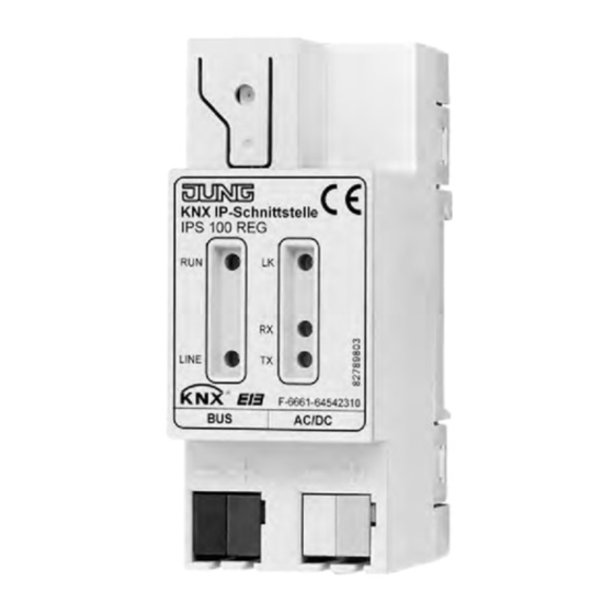
The front of the device has LED displays to signal readiness, KNX communication and IP communication. Due to the supported KNX standard, the device can be configured simply and put into operation via the ETS. Art.-No.: IPS 100 REG Page 3 of 25... -
Page 4: Accessories
Product definition 1.3 Accessories Power supply AC 24V~ Art.-No.: WSSV10 Art.-No.: IPS 100 REG Page 4 of 25... -
Page 5: Fitting, Electrical Connection And Operation
Failure to observe the instructions may cause damage to the device and result in fire and other hazards. Use the safety transformer according to DIN EN 61558-2-6 (VDE 0570 Part 2-6) or bell transformer according to DIN EN 61558-2-8 (VDE 0570 Part 2-8). Art.-No.: IPS 100 REG Page 5 of 25... -
Page 6: Device Components
If the programming button (10) is actuated, the "TX" LED signals the type of IP address assignment to the device for 10 seconds: 1x flash: Fixed IP address 2x flash: DHCP 3x flash: AutoIP (9) Programming LED (red) (10) Programming button Art.-No.: IPS 100 REG Page 6 of 25... -
Page 7: Fitting And Electrical Connection
Ethernet" according to IEEE 802.3af - or through the external power supply via the second terminal block (Recommendation: White-yellow connection terminal). When the external voltage supply is connected, the device switches automatically to this. Art.-No.: IPS 100 REG Page 7 of 25... - Page 8 Fitting, electrical connection and operation picture 2: Electrical connection of the bus line and the external power supply Connection example with additional power supply (e.g. suitable bell transformer) Art.-No.: IPS 100 REG Page 8 of 25...
- Page 9 If the red LED "TX" (8) is lit up, the device is transmitting data to the network. i Depending on application, access requirements, data security and data volume it may be advisable to install independent network paths for individual services using the IP network. Art.-No.: IPS 100 REG Page 9 of 25...
- Page 10 Fitting, electrical connection and operation i The KNX bus connection and the terminal block for the external power supply are galvanically separated from the Ethernet connection. Art.-No.: IPS 100 REG Page 10 of 25...
-
Page 11: Commissioning
(10) on the device is pressed for longer than 10 seconds. All the addresses are then set to the default value 15.15.255 and the programming LED goes out (9). New address assignment is then possible. Art.-No.: IPS 100 REG Page 11 of 25... -
Page 12: Technical Data
DC 48 V Power consumption max. 0.8 W IP connection mode RJ45 socket IP communication Ethernet 10BaseT IP transmission rate 10 Mbit/s Protocols ARP, ICMP, IGMP, UDP/IP, DHCP KNXnet/IP Core, Tunneling, Device Management Art.-No.: IPS 100 REG Page 12 of 25... -
Page 13: Software Description
Communication / IP / IP interface Configuration: S-mode standard PEI type: "00" / "0" PEI connector: No connector Application program: No. Short description Name Version from mask version Data interface KNXnet/IP IP interface 720001 Art.-No.: IPS 100 REG Page 13 of 25... -
Page 14: Software "Ip Interface 720001
Simple connection of visualisation systems and facility management systems. Communication between buildings and sites (e.g. networking of sites). Simple parameter configuration and commissioning (device programming via the bus) using ETS 2, Version 1.2 or higher, or ETS 3. Art.-No.: IPS 100 REG Page 14 of 25... -
Page 15: Software Information
Programming button for longer than 6 seconds. The transition to the delivery state is displayed by the Programming LED flashing rapidly. This operation causes all the parameter settings to be deleted. Art.-No.: IPS 100 REG Page 15 of 25... - Page 16 Note on this product documentation This product documentation describes the device with the release code "R2" on the device label. Separate product documentation is available for older device variants (no release code). Art.-No.: IPS 100 REG Page 16 of 25...
-
Page 17: Functional Description
If the Programming button is pressed on the device, the "TX" LED signals the type of IP address assignment to the device for 10 seconds: 1x flash: Fixed IP address 2x flash: DHCP 3x flash: AutoIP Art.-No.: IPS 100 REG Page 17 of 25... -
Page 18: Communication Parameters In The Ets
"Tools -> Options -> Communication" (picture 4). picture 4: Options dialog of the communication properties of ETS3 Select the "Configure interface" button. The "ETS Connection Manager" window opens (picture 5). Art.-No.: IPS 100 REG Page 18 of 25... - Page 19 Create a new connection. Then press the "New" button. Give the new connection a unique name. Select "Eibnet/IP" as the type (picture 6). Then ETS will search the IP data network automatically for available IP communication devices. picture 6: Creating the new connection as EIBnet/IP Art.-No.: IPS 100 REG Page 19 of 25...
- Page 20 (similar to the local physical address with a RS232 or USB connection). For this, select the new KNXnet/IP connection as the interface in the Options dialog of the Communication parameters (picture 8) and click the "Settings" button. Art.-No.: IPS 100 REG Page 20 of 25...
- Page 21 The physical address "15.15.255" is preset in the delivery state. Clicking the "OK" button terminates the configuration of the IP data interface. The IP connection can then be used. picture 9: Settings of local communication device Art.-No.: IPS 100 REG Page 21 of 25...
-
Page 22: Parameters
The four bytes of the subnet mask are set individually. When combined, this produces the known dot notation of a subnet mask: Byte 1 . Byte 2 . Byte 3 . Byte 4. h IP Config 2 Art.-No.: IPS 100 REG Page 22 of 25... - Page 23 The four bytes of the IP address are set individually. When combined, this produces the known dot notation of an IP address: Byte 1 . Byte 2 . Byte 3 . Byte 4. Art.-No.: IPS 100 REG Page 23 of 25...
-
Page 24: Appendix
ETS ............. 15 ETS search paths ........13 Fitting the device ........7 IP connection ......... 9 Loading the physical address ....11 power supply ......... 7 Art.-No.: IPS 100 REG Page 24 of 25... - Page 25 Appendix ALBRECHT JUNG GMBH & CO. KG Volmestraße 1 D-58579 Schalksmühle Telefon: +49.23 55.8 06-0 Telefax: +49.23 55.8 06-1 89 E-mail: mail.info@jung.de Internet: www.jung.de www.jung-katalog.de Art.-No.: IPS 100 REG Page 25 of 25...
Need help?
Do you have a question about the IPS 100 REG and is the answer not in the manual?
Questions and answers