
Related Manuals for Lifetime 90230


Summary of Contents for Lifetime 90230
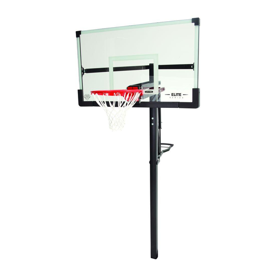
- Page 1 MODEL N° 90230 OWNER’S MANUAL Keep this Product ID Number and use when contacting Customer Service:...
- Page 2 REGISTER YOUR PRODUCT ONLINE AT WWW.LIFETIME.COM At Lifetime, we are committed to providing innovative and quality products. While registering, you will have the opportunity to give us your feedback. Your input is valuable to us. Lifetime’s Promise to You: REGISTER today! Save this owner’s manual for future reference and in the event that...
- Page 3 SAFETY INSTRUCTIONS FAILURE TO FOLLOW THESE WARNINGS MAY RESULT IN SERIOUS INJURY OR PROPERTY DAMAGE AND WILL VOID WARRANTY. Most injuries are caused by misuse and/or not following instructions. Use caution when using this product. BEFORE BEGINNING ASSEMBLY...
- Page 4 SAFE HANDLING OF GLASS BACKBOARDS BEFORE & DURING ASSEMBLY GENERAL HANDLING & CARE HANDLING BROKEN GLASS At the fi rst sign of breakage: REMOVING BACKBOARD FROM SYSTEM WARNING least...
- Page 5 TOOLS AND PARTS REQUIRED FOR THIS ASSEMBLY 9/16” Wrench Phillips Screwdriver 1/2” Socket Wrench 3/4” Socket Wrench 5/16” Allen Wrench 9/16” Socket Wrench 1/4” Allen Wrench 3/8” Alen Wrench Level Ladder Shovel Cement Mix Tape Measure Rebar Tape Rubber Mallet Bricks *Three adults required to complete assembly*...
- Page 6 ASSEMBLY GUIDES Refer to the following areas throughout the instructions to assist in the assembly process: This area is located at the top, TOOLS AND HARDWARE REQUIRED FOR THIS PAGE left-hand corner of the page and indicates which tools and hardware are needed to complete the assembly steps on a page.
-
Page 7: Parts List
PARTS LIST Item Description... -
Page 8: Hardware List
HARDWARE LIST Item Description Pole Assembly Hardware Backboard & Rim Assembly Hardware Backboard to Pole Assembly Hardware Handle Assembly Hardware... -
Page 9: Parts Identifier
PARTS IDENTIFIER Parts shown at 10% of Actual Size... - Page 10 PARTS IDENTIFIER Part shown at 5% of Actual Size Parts shown at Actual Size...
- Page 11 PARTS IDENTIFIER Parts shown at 25% of Actual Size...
-
Page 12: Hardware Identifier
HARDWARE IDENTIFIER POLE ASSEMBLY HARDWARE Hardware shown at Actual Size BACKBOARD TO RIM ASSEMBLY HARDWARE Hardware shown at Actual Size... - Page 13 HARDWARE IDENTIFIER BACKBOARD TO POLE ASSEMBLY HARDWARE Hardware shown at Actual Size 7”...
- Page 14 HARDWARE IDENTIFIER HANDLE ASSEMBLY HARDWARE Hardware shown at Actual Size 7” 5.4”...
-
Page 15: Hardware Required
POLE ASSEMBLY HARDWARE REQUIRED Hardware shown at Actual Size PARTS REQUIRED Parts shown is not to scale Part shown at 25% of Actual Size TOOLS REQUIRED 9/16” Socket Wrench 5/16 Allen Wrench Tape Measure Cement Mix Bricks 30” Rebar Level Tape Shovel... - Page 16 TOOLS AND HARDWARE REQUIRED FOR THIS PAGE NO HARDWARE REQUIRED FOR THIS PAGE Note: A Ground Sleeve is available as an alternative to cementing the Pole into the ground. Please contact Customer Service for more information.
- Page 17 TOOLS AND HARDWARE REQUIRED FOR THIS PAGE 9/16” 5/16” 3/8” x 4 1/2” Bolts (CTY) Pole (ALG) 1/2” x 3.91” Spacers (ANE) Pole Bracket (ALL) 3/8” Nylock Nuts (CUB) Large holes Small holes Note: Make sure the Warning Sticker and the Pole Bracket face opposite directions.
- Page 18 TOOLS AND HARDWARE REQUIRED FOR THIS PAGE 30” Rebar NO HARDWARE REQUIRED FOR THIS PAGE Rebar Pole Caps (ALM) Alignment Frame (BGW)
- Page 19 TOOLS AND HARDWARE REQUIRED FOR THIS PAGE NO HARDWARE REQUIRED FOR THIS PAGE do not Note: Make sure the Pole Cap stays on the bottom of the Pole throughout the entire cementing process. 16”...
- Page 20 TOOLS AND HARDWARE REQUIRED FOR THIS PAGE 30” Rebar NO HARDWARE REQUIRED FOR THIS PAGE Pole WARNING Note: Make sure the Pole Bracket faces away from the playing surface.
- Page 21 TOOLS AND HARDWARE REQUIRED FOR THIS PAGE NO HARDWARE REQUIRED FOR THIS PAGE Note: Slope the concrete away from the Pole to prevent water buildup around the Pole. 1.10 Alignment Frame (BGW) Playing Surface TOP VIEW...
- Page 22 TOOLS AND HARDWARE REQUIRED FOR THIS PAGE NO HARDWARE REQUIRED FOR THIS PAGE 1.11 Alignment Frame (BGW) Note: STOP HERE! The concrete must cure for at least 72 hours (3 days) before installing the rest of the system. In humid climates or wet weather, allow additional time for the concrete to cure.
- Page 23 BACKBOARD TO RIM ASSEMBLY HARDWARE REQUIRED Hardware shown at Actual Size PARTS REQUIRED Part shown at 5% of Actual Size Part shown at 10% of Actual Size...
- Page 24 BACKBOARD TO RIM ASSEMBLY PARTS REQUIRED Part shown at 25% of Actual Size BGR (x1) Washer Plate TOOLS REQUIRED Phillips Screwdriver 1/2” Wrench...
- Page 25 TOOLS AND HARDWARE REQUIRED FOR THIS PAGE 1/2” Rim Mount Bracket (DJA) Rim Spacer (BGY) Rim (ALX) WARNING...
- Page 26 TOOLS AND HARDWARE REQUIRED FOR THIS PAGE 1/2” Washer Plate (BGR) Rim Cover Plate (AMA)
- Page 27 TOOLS AND HARDWARE REQUIRED FOR THIS PAGE 1/2” Backboard (AJI) Front View Rear View Note: Do not overtighten the hardware so that the 7/16”Rubber Washer bulges outward as shown. Incorrect Correct...
- Page 28 TOOLS AND HARDWARE REQUIRED FOR THIS PAGE 1/2” Rim Mount Bracket (DJA)
- Page 29 BACKBOARD TO POLE ASSEMBLY HARDWARE REQUIRED Hardware shown at Actual Size 7”...
- Page 30 BACKBOARD TO POLE ASSEMBLY PARTS REQUIRED Parts shown at 10% of Actual Size Parts shown at 10% of Actual Size AKD (x2) Upper Extension Arm DIR (x2) Middle Extension Arm BGP (x2) Lower Extension Arm Parts shown at 25% of Actual Size Parts shown at Actual Size TOOLS REQUIRED 3/4”...
- Page 31 TOOLS AND HARDWARE REQUIRED FOR THIS PAGE NO HARDWARE REQUIRED FOR THIS PAGE Tie Plate (BLC) Lower Extension Arm (BGP) Tie Plate (BLC) Lower Extension Arm (BGP)
- Page 32 TOOLS AND HARDWARE REQUIRED FOR THIS PAGE 1/2” Lower Extension Arms (BGP) 5/16” x 3/4” Thread-Cutting Bolts (AQB) Tie Plate (BLC) Extension Arm Caps (AQC) Note: Repeat Sec 3.1-3.4 to assemble the Middle Extension Arms (DIR) .
- Page 33 TOOLS AND HARDWARE REQUIRED FOR THIS PAGE 7” 3/4” 3/8” Dark Lithium Grease (AJZ) 1/2” x 7” Bolt (CUG) Lower Extension Arms (BGP) Rim Mounting Bracket (DJA) Note: Tighten the 1/2” Nylock Nut (CYF) until it is fl ush with the end of the Bolt.
- Page 34 TOOLS AND HARDWARE REQUIRED FOR THIS PAGE 7” 3/4” 3/8” Dark Lithium Grease (AJZ) 1/2” x 7” Bolt (CUG) Middle Extension Arms (DIR) Rim Mounting Bracket (DJA) Note: Tighten the 1/2” Nylock Nut (CYF) until it is fl ush with the end of the Bolt.
- Page 35 TOOLS AND HARDWARE REQUIRED FOR THIS PAGE 3/4” 3/8” Upper Extension Arms (AKD) Upper Extension Arms (AKD)
- Page 36 TOOLS AND HARDWARE REQUIRED FOR THIS PAGE 7” 3/4” 3/8” CAUTION: HAVE TWO ADULTS HOLD THE BACKBOARD IN PLACE UNTIL ASSEMBLY HAS BEEN COMPLETED! Dark Lithium Grease (AJZ) 1/2” x 7” Bolt (CUG) Pole Cap (ALM) Pole (ALG) Upper Extension Arms (AKD) ANZ ANZ WARNING Note: Tighten the 1/2”...
- Page 37 TOOLS AND HARDWARE REQUIRED FOR THIS PAGE 7” 3/4” 3/8” CAUTION: HAVE TWO ADULTS HOLD THE BACKBOARD IN PLACE UNTIL ASSEMBLY HAS BEEN COMPLETED! 3.10 Dark Lithium Grease (AJZ) 1/2” x 7” Bolt (CUG) Middle Extension Arms (DIR) Pole (ALG) Note: Tighten the 1/2”...
- Page 38 TOOLS AND HARDWARE REQUIRED FOR THIS PAGE 7” 3/4” 3/8” CAUTION: HAVE TWO ADULTS HOLD THE BACKBOARD IN PLACE UNTIL ASSEMBLY HAS BEEN COMPLETED! 3.11 Dark Lithium Grease (AJZ) 1/2” x 7” Bolt (CUG) Lower Extension Arms (BGP) Note: Tighten the 1/2” Nylock Nut (CYF) until it is fl ush with the end of the Bolts.
- Page 39 TOOLS AND HARDWARE REQUIRED FOR THIS PAGE 7” 3/4” 3/8” CAUTION: HAVE TWO ADULTS HOLD THE BACKBOARD IN PLACE UNTIL ASSEMBLY HAS BEEN COMPLETED! 3.12 Note: Tighten the 1/2” Nylock Nut (CYF) until it is fl ush with the end of the Bolt.
- Page 40 HANDLE ASSEMBLY HARDWARE REQUIRED Hardware shown at Actual Size 7” 5.4”...
- Page 41 HANDLE ASSEMBLY PARTS REQUIRED Parts shown at 10% of Actual Size AKI (x1) Handle Assembly Parts shown at 25% of Actual Size Parts shown at Actual Size TOOLS REQUIRED 1/2”, 3/4”, 15/16” 1/4”, 3/8” Allen Rubber Mallet Wrench Wrench...
- Page 42 TOOLS AND HARDWARE REQUIRED FOR THIS PAGE 1/2” 1/4” Gas Spring Cover (AKG) Gas Spring (AKF) Gas Spring Cover (AKG) Gas Spring (AKF) Pole Bracket (ALL) Note: Tighten the 5/16” Nylock Nut (CYN) until it is fl ush with the end of the Bolt.
- Page 43 TOOLS AND HARDWARE REQUIRED FOR THIS PAGE 5.4” 3/4” 3/8” Dark Lithium Grease (AJZ) 1/2” x 5.4” Bolt (DFR) Handle Brackets (CYA) Note: DO NOT overtighten the hardware. The Handle Brackets should rotate freely.
- Page 44 TOOLS AND HARDWARE REQUIRED FOR THIS PAGE 3/4” 3/8” Dark Lithium Grease (AJZ) 1/2” x 3” Bolt (DFS) Handle (AKI) Handle Brackets (CYA) 1/2” Plastic Washer (AEG) Note: Tighten the 1/2” Centerlock Nut (AAX) until it is fl ush with the end of the Bolt. Leave a very slight amount of play in the bolt so the handle can move properly.
- Page 45 TOOLS AND HARDWARE REQUIRED FOR THIS PAGE NO TOOLS REQUIRED FOR THIS PAGE White Silicone Grease (AKH) Trigger Pin (DIN) Gas Spring (AKF) CAUTION...
- Page 46 TOOLS AND HARDWARE REQUIRED FOR THIS PAGE 3/4” 3/8” White Silicone Grease (AKH) 1/2” x 3” Bolt (DFS) 1/2” Large Plastic Washers (DIQ) CAUTION Note: Tighten the Bolt (DFS) so there is some slight play where the Handle meets the Brackets. Tube Cap (DIO) Power Flex Spring Assembly (DIU)
- Page 47 TOOLS AND HARDWARE REQUIRED FOR THIS PAGE 3/4” 3/8” White Silicone Grease (AKH) 5/8” x 3” Bolt (DFS) Power Flex Spring Assembly (DIU) 1/2” Centerlock Nut (AAX) CAUTION Note: Tighten the 1/2” Centerlock Nut (AAX) until it is fl ush with the end of the Bolt.
- Page 48 TOOLS AND HARDWARE REQUIRED FOR THIS PAGE 7” 15/16” 3/8” Dark Lithium Grease (AJZ) 5/8” x 7” Bolt (DXL) PowerFlex Spring Assembly (DIU) Lower Extension Arms (AKB) WARNING Note: Tighten the 5/8” Nylock Nut (CYG) until it is fl ush with the end of the Bolt. Note: Use a 1/2”...
- Page 49 TOOLS AND HARDWARE REQUIRED FOR THIS PAGE NO TOOLS OR HARDWARE REQUIRED FOR THIS PAGE White Silicone Grease (AKH) 4.10 CAUTION...
- Page 50 FINAL ASSEMBLY HARDWARE REQUIRED PARTS REQUIRED Parts shown at 10% of Actual Size Parts shown at 25% of Actual Size TOOLS REQUIRED...
- Page 51 TOOLS AND HARDWARE REQUIRED FOR THIS PAGE NO HARDWARE REQUIRED FOR THIS PAGE (AKZ) Rim (ALX) Note: If a replacement Net is needed, please call our Customer Service Department. Our Nets are shorter than average to reduce the risk of entanglement. Gas Spring Cover (AKG) Gas Spring (AJR) Height Sticker (AKP)
- Page 52 OPERATION OF HEIGHT ADJUSTMENT SYSTEM To Adjust the Height of the Hoop: POLE CARE AND SYSTEM MAINTENANCE IF RUST HAS PENETRATED THROUGH THE POLE ANYWHERE, REPLACE IT IMMEDIATELY!
- Page 53 NOTES...
- Page 54 NOTES...
- Page 55 ® ENHANCE YOUR LIFETIME PURCHASE BY ADDING ACCESSORIES OR OTHER GREAT PRODUCTS: To purchase accessories or other Lifetime Products, visit us at: www.lifetime.com Or call: 1-800-424-3865...
- Page 56 à l’anneau, au panneau ni aux leviers sous aro, el tablero ni los brazos de elevación, ya que esto puede peine d’endommager l’équipement et d’annuler la garantie. www.lifetime.com #FS16500 10/12/2004...
-
Page 57: Warranty Information
THE MANUFACTURER RESERVES THE RIGHT TO MAKE SUBSTITUTIONS TO WARRANTY CLAIMS IF PARTS ARE UNAVAILABLE OR OBSOLETE. ALL WARRANTY CLAIMS MUST BE ACCOMPANIED BY A SALES RECEIPT. REPORT PRODUCT DEFECTS IN WRITING TO: To register the product, visit our Web site at www.lifetime.com www.lifetime.com...
Need help?
Do you have a question about the 90230 and is the answer not in the manual?
Questions and answers