Midea COMPACT Series Service Manual
Hide thumbs
Also See for COMPACT Series:
- User manual ,
- Service manual (40 pages) ,
- Service manual (34 pages)
Table of Contents
Advertisement
Service Manual
(The picture in this service manual is only for reference, and specific appearance and configuration are
subject to the real product)
COMPACT SERIES
Applicable Models
UR-PC140-DQ
Prepared by
Reviewed by
Approved by
1
Service Manual_2018-V1.0
Model Code
22033210000081
R&D:Tian Song
QA:Ke Bingfei
SVC:Zhang Kun
R&D: Zhang Huawei
SVC:Guang Taoshuai
Advertisement
Table of Contents

Related Manuals for Midea COMPACT Series


Summary of Contents for Midea COMPACT Series
- Page 1 Service Manual_2018-V1.0 Service Manual COMPACT SERIES Applicable Models Model Code UR-PC140-DQ 22033210000081 R&D:Tian Song Prepared by QA:Ke Bingfei Reviewed by SVC:Zhang Kun R&D: Zhang Huawei Approved by SVC:Guang Taoshuai (The picture in this service manual is only for reference, and specific appearance and configuration are...
- Page 2 Manufacturers or distributors are not responsible for the content of the Manual and interpretation thereof. Midea Refrigerators Technical Maintenance Manual Copyright @2017 All rights reserved. Replication of all or part of the Manual in any forms shall not be allowed without written approval by the Overseas Sales Corporation of Midea Refrigerators.
-
Page 3: Table Of Contents
Service Manual_2018-V1.0 Contents 1. SAFETY WARNING CODE ........................... 5 ........................... 5 1.1 W ARNING FOR OPERATION SAFETY 1.2 S ......................... 7 AFETY INSTRUCTION FOR REFRIGERANT 2. DESCRIPTION FOR PRODUCT FEATURES ..................... 8 3. INSTALLATION AND COMMISSIONING ......................9 3.1 H ................................... - Page 4 Service Manual_2018-V1.0 ..............................24 8.7 C OMPRESSOR CASE 8.8 D ............................29 ISPLAY CONTROL BOARD ............................29 8.9 M AIN CONTROL BOARD 8.10 B ................................ 29 AR COUNTER ..............................29 8.11 W ATER DISPENSER 8.12I ................................29 CE MAKER 9. FUNCTION AND OPERATION ..........................30 ..............................
-
Page 5: Safety Warning Code
Service Manual_2018-V1.0 1. Safety Warning Code 1.1 Warning for operation safety Important Safety Instructions CAUTION RISK OF ELECTRIC SHOCK DO NOT OPEN This symbol indicates that dangerous voltage constituting a risk of electric shock is present within your freezer. This symbol indicates that there are important operating and maintenance instructions in the literature accompanying your freezer. - Page 6 Service Manual_2018-V1.0 CONNECTING ELECTRICITY Electrical Shock Hazard. Failure to follow these instructions can Plug into a grounded 3-prong outlet. result in death, fire, or electrical shock. Do not remove the ground prong. Do not use an adapter. WARNING Electric Shock Hazard Failure to follow these instructions can result in electric shock, fire, or death.
-
Page 7: Safety Instruction For Refrigerant
Service Manual_2018-V1.0 13) Do not store or use gasoline or any flammable liquids inside or in the vicinity of this freezer. 14) Do not use extension cords or ungrounded (two-prong) adapters with this freezer. If the power cord is too short, have a qualified electrician install an outlet near the freezer. Use of an extension cord can negatively affect the freezer’s performance. -
Page 8: Description For Product Features
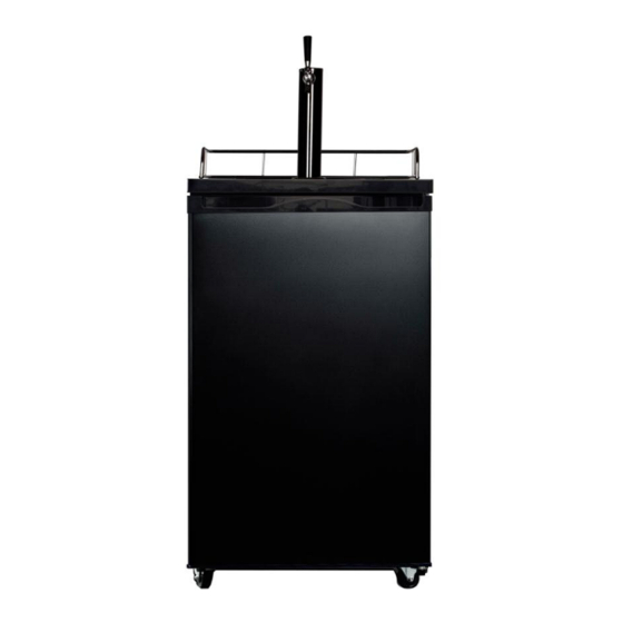
Service Manual_2018-V1.0 2. Description for product features This product is provided with following features: 1)Integrative refrigeration chamber 2)Mechanical control 3)Polisher black tower with stainless steel trim 4)Holds most 1/2 and 1/4 size kegs... -
Page 9: Installation And Commissioning
Service Manual_2018-V1.0 3. Installation and commissioning 3.1 Handling Handling 1)Protect the refrigerator in moving it,Same as shown as left photo, please move it by handcart with cushion 2)Remove all packing materials and bottom cushion, the n move into house for placement 3)After moving it to appropriate location, wait for 2 hours before power on. -
Page 10: Door Reversal
Service Manual_2018-V1.0 If the refrigerator cannot be placed steadily, adjust the footing to level it. 3.5 Door reversal Door reversal 1)Disassembly the top cover fix screw, remove the seal plate of top cover. 1) 2)Disassembly the screw that is fix upper hinge and top cover, remove the top cover. - Page 11 Service Manual_2018-V1.0 4)Reversion the bottom hinge. 5)Disassembly left upper hinge, install fixed axis to upper hinge, install axle sleeve to the door.
-
Page 12: Installation Of Handle
Service Manual_2018-V1.0 6)Assembly the left upper hinge and right upper hinge. 2) 7)Assembly the screw that is fix top cover. 3.6 Installation of handle Installation of handle Installation of handle None 3.7 Installation of door lock Installation of door lock Installation of door lock None... -
Page 13: Adjustment To Level The Door
Service Manual_2018-V1.0 3.8 Adjustment to level the door Adjustment to level the door Adjustment to level the door None 3.9 Adjustment to shelves Adjustment to shelves Adjustment to shelves None... -
Page 14: Terms
Service Manual_2018-V1.0 4. Terms 4.1 Definition of model (None) 4.2 Location of nameplate (None) -
Page 15: Product Specification
Service Manual_2018-V1.0 5. Product specification 5.1 Type specification(None) 5.2 Electrical parameters None None None Product Name UR-PC140-DQ Product Code 22033210000081 None None None Item Specification Specification Specification Specification Compressor Compressor FZ59E1G None None None QP2-4R7 None None None Starter(PTC) Overload DRB29T61A1 None None... -
Page 16: Inside Temperature
Service Manual_2018-V1.0 refrigerator door 5.3 Inside temperature Temperature tolerance ≤ 2 The highest ( Lowest ( Compartment None None Freezing Refrigerating Variable temperature None None 5.4 Defrosting parts Item Initial defrosting period Normal defrosting period Defrosting period None None None None Defrosting sensor Defrosting temperature... -
Page 17: Circuit Diagram
Service Manual_2018-V1.0 5.5 Circuit diagram... -
Page 18: Internal View And Dimension
Service Manual_2018-V1.0 6. Internal view and dimension 6.1 Main parts and their names Freezer chamber Refrigerator chamber ❶ Thermostat None ❷ Shelf ❸ Evaporator ❹ Beer can bottom pad... -
Page 19: External Dimension
Service Manual_2018-V1.0 6.2 External dimension Description Code Size (mm) Height to Top of Case Width Depth w/Handles Depth (Total with Door Open) 1140 Width (door open 90 deg. w/ handle) -
Page 20: Refrigerating Piping System And Circulating Route Of Cooling Air
Service Manual_2018-V1.0 7. Refrigerating piping system and circulating route of cooling air 7.1 Refrigerating piping system ❶Compressor→❷ Exhaust transition pipe→❸ondenser→❹ Dry filter→❺ Capillary tube→❻ Evaporator→❼ Suction tube→ ❶Compressor 7.2 Circulating route of cooling air(None) -
Page 21: Dismantling Of Parts
Service Manual_2018-V1.0 8. Dismantling of parts 8.1 Parts on the door Door seal Open the wine cabinet door; Take the door seal ①out of door liner. Guardrail Guardrail None Door stopper Door stopper None rollover beam rollover beam None 8.2 Parts inside the refrigerator Shelf Lift up the shelf with a proper force and pull it out towards yourself. -
Page 22: Light System
Service Manual_2018-V1.0 8.3 Light system Light Light None Light switch Light switch None Pilot light Pilot light None Fresh light Fresh light None 8.4 Air duct components refrigerating chamber Air duct components refrigeratingchamber Air duct components refrigeratingchamber None 8.5 Air duct components in freezing chamber and fan motor Disassembly and installation of Air duct Disassembly and installation of Air duct None... - Page 23 Service Manual_2018-V1.0 Take down screws and gaskets on the evaporator. Remove the welding on inlet and outlet tubes. Components on the evaporator None Sensor Sensor in freezing chamber None Sensor in refrigerating chamber None Ambient temperature sensor None Sensor in Variable temperature chamber None Thermostat 1) Disassembly the screw that is fix the thermostat box.
-
Page 24: Compressor Case
Service Manual_2018-V1.0 2)Pull out the thermostat fix plate and knob, remove the wiring and thermostat from the thermostat box. 8.7 Compressor case Rear cover and compressor case 1)Remove by cross screwdriver the screws fixing back cover plate of compressor chamber anticlockwise. 2)Take the back cover plate of compressor chamber upward. - Page 25 Service Manual_2018-V1.0 2) Slowly tilt the refrigerator forward, relying on the wall or a solid enough object, leaving space to facilitate the operation. For safety, it should be carried by someone to prevent its falling. 3)Cut off the compressor pipeline.-❶Cut off the process pipeline.-❷Cut off the low-pressure muffler.-❸Cut off the high-pressure exhaust pipe.
- Page 26 Service Manual_2018-V1.0 6)Remove the protective cover -Pry the protective cover slowly from the upper part, -Pull it out and remove it. 7)Remove the starter and protector Unplug the starter and protector (you can use a screwdriver to pry it slowly) 8)Loosen the screw of the compressor bottom plate, remove the floor together with the compressor from the box.
- Page 27 Service Manual_2018-V1.0 10)Use Pipe cutter cut off the condenser tube❽, then Shear off capillary ❾ by the capillary tube scissors. 11)Replace the compressorand welding the compressor pipeline.-❿Welding the process pipeline.-⓫Welding the low-pressure muffler.-⓬Welding the high-pressure exhaust pipe. 12)Replace the filter, Cu-Fe tubes welding ⓭ used Ag welding rod, Cu-Cu tubes welding ⓮...
- Page 28 Service Manual_2018-V1.0 15)Use the vise grip pliers clamp the middle of the process pipe, then seal welding process tube⓯⓰. Condenser fan motor Condenser fan motor None Standby condenser Standby condenser None Piping system in the compressor case ❶ Compressor ❺ Dry filter ❻...
-
Page 29: Display Control Board
Service Manual_2018-V1.0 1)Pull out the drain tray 2)Replace the drain tray, the reverse process can complete installation. 8.8 Display control board Display control board None Display control board 8.9 Main control board Main control board Main control board None 8.10 Bar counter Bar counter Disassembly and installation of bar counter None... -
Page 30: Function And Operation
Service Manual_2018-V1.0 9. Function and operation 9.1 Operation panel Icons Button Temperature control knob None 9.2 Temperature control Direct cooling mechanical refrigerator, through the thermostat knob to adjust the stalls. Turn the temperature control knob to 6gear, the internal temperature of the refrigerator becomes lower. Turn the temperature control knob to 1gear, the internal temperature of the refrigerator becomes higher. -
Page 31: Circuit Description
Service Manual_2018-V1.0 10. Circuit description 10.1 Power Supply(None) 10.2 Test circuit for door switch(None) 10.3 Temperature test circuit(None) 10.4 Freezer chamber fan motor circuit (None) 10.5 refrigerating chamber fan motor circuit (None) 10.6 Condensation fan circuit (None) 10.7 Fan motor circuit of the ventilation door(None) 10.8 Resistance value of the sensor (R/T) (None) -
Page 32: Troubleshooting Method
Service Manual_2018-V1.0 11. Troubleshooting Method 11.1 Not cooling... -
Page 33: Not Working Of Compressor
Service Manual_2018-V1.0 11.2 Not working of compressor 11.3 Thermostat malfunction-Undercooling... -
Page 34: Light Is Not On
Service Manual_2018-V1.0 11.4 Light is not on 11.5 Noise... -
Page 35: Figures And Details Of Repair Parts(Documents Are Provided Separately)
Service Manual_2018-V1.0 12. Figures and details of repair parts(Documents are provided separately) 12.1 Figures 12.2 List of parts and components... -
Page 36: Appendix
Service Manual_2018-V1.0 13. Appendix 13.1 Refrigerator maintenance tooling and equipment and material Tooling Name Main Usage Photo screw assemble and Phillips screwdriver disassemble slotted screw and rivet assemble and screwdriver/scraper disassemble hinge and compressor screw Socket spanner 5/16″ assemble and disassemble display panel and air duct cover Sucker disassemble... - Page 37 Service Manual_2018-V1.0 Capillary tube scissors Shear capillary Knife assistive tool Pipe cutter, Flaring Pipe cutting,flaring device Electronic digital Test temperature thermometer Measurement with resistance, Multi meter voltage, current and so on. Equipment Name Main Usage Photo Vacuum pump with vacuum pumping gauge Electronic scale weighing refrigerant/gas...
- Page 38 Service Manual_2018-V1.0 Connection process pipeline, Quick coupling vacuum or charge refrigerant will be used. Soldering gun heating and welding welding point leakage detect, if hand leak detector no, use soap-suds Material Name Main Usage Photo Process pipeline Charge the refrigerant Involving a system failure to be Dry filter...
- Page 39 Service Manual_2018-V1.0 Aluminium-Aluminium tubes Transition copper pipe welding, maintain lengthen tubes The symbol on the product or its packaging indicates that this product must not be disposed of with your other household waste. Instead, it is your responsibility to dispose of your waste equipment by handing it over to a designated collection point for the recycling of waste electrical and electronic equipment.
- Page 40 Service Manual_2018-V1.0 local authority, or where you purchased your product. MIDEA appliances after sales website For more information about Midea appliances after sales, please visit the tsp.midea.com tsp.midea.com For more information about the service manual, please visit the For more information about the EV and SBOM, please visit the tsp.midea.com...
Need help?
Do you have a question about the COMPACT Series and is the answer not in the manual?
Questions and answers