
Related Manuals for Black Box LBH3050A


Summary of Contents for Black Box LBH3050A
- Page 1 STEP X - Name of Step QUICK START GUIDE LBH3050A, LBH3080A INDUSTRIAL SWITCHES 24/7 TECHNICAL SUPPORT AT 877.877.2269 OR VISIT BLACKBOX.COM...
-
Page 2: Step 1 - Package Includes
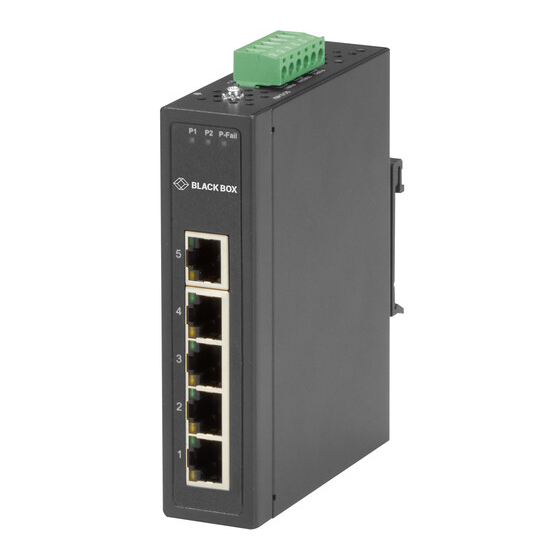
STEP 1 - Package Includes WHAT’S INCLUDED • (1) LBH3050A OR LBG3080A INDUSTRIAL SWITCH • (2) WALLMOUNTING BRACKETS WITH SCREWS • (1) DIN RAIL MOUNTING BRACKET WITH SCREWS • THIS QUICK START GUIDE... - Page 3 STEP 2A - LBH3050A Hardware Overview TABLE 1. LBH3050A COMPONENTS NUMBER DESCRIPTION 5, 6, 7 6-pin terminal block for power Link/Activity LED Speed LED (5) RJ-45 connectors Power 1 LED Power 2 LED Power Fail LED...
- Page 4 STEP 2B - LBH3080A Hardware Overview TABLE 2. LBH3080A COMPONENTS NUMBER DESCRIPTION 5, 6, 7 6-pin terminal block for power Link/Activity LED Speed LED (8) RJ-45 connectors Power 1 LED Power 2 LED Power Fail LED...
-
Page 5: Step 3 - Connect The Power
STEP 3 - Connect the Power POWER CONNECTION STEPS The LBH3050A and LBH3080A switches support dual +12 to 48 VDC power inputs and changes relay status when the power fails. 1. Insert the positive and negative wires into the V+ and V- contacts on the terminal block connector. - Page 6 STEP 4A - DIN Rail Mounting INSTALLING THE DIN RAIL KIT Attach the DIN rail bracket to the DIN rail using the included screws. See Figure A. REMOVING THE DIN RAIL KIT Remove the screws from the DIN rail. 2. Lift the switch up and off from the DIN rail. See Figure B.
- Page 7 STEP 4B - Wallmounting WALLMOUNTING STEPS Using the included screws, attach the wallmount brackets to the switch. 2. With the brackets attached, hang the switch on the nails on the wall.
- Page 8 STEP X - Name of Step COPYRIGHT 2017 BLACK BOX CORPORATION. ALL RIGHTS RESERVED.
Need help?
Do you have a question about the LBH3050A and is the answer not in the manual?
Questions and answers