
Subscribe to Our Youtube Channel
Related Manuals for Black Box LBH Series


Summary of Contents for Black Box LBH Series
- Page 1 STEP X - Name of Step QUICK START GUIDE LBH AND LMC SERIES INDUSTRIAL SWITCH 24/7 TECHNICAL SUPPORT AT 877.877.2269 OR VISIT BLACKBOX.COM...
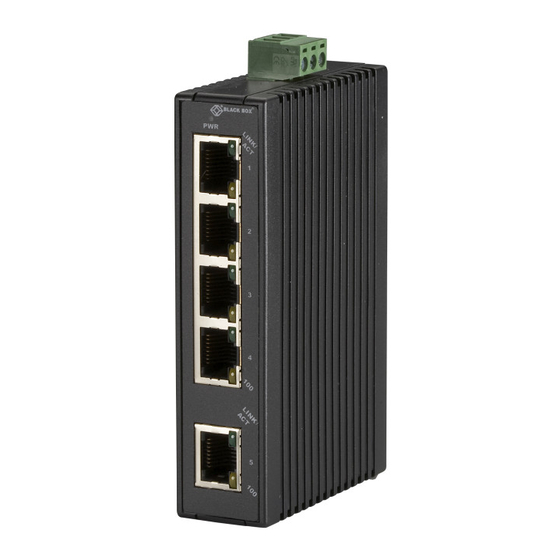
- Page 2 STEP 1 - Hardware Description INDUSTRIAL MEDIA CONVERTERS INDUSTRIAL MINI SWITCHES • LMC270A-MM-SC (SC FIBER MULTIMODE) • LBH120A-H (TWISTED PAIR CONNECTORS) • LMC270A-MM-ST (SC FIBER MULTIMODE) • LBH120A-H-SC (SC FIBER CONNECTORS) • LMC270A-SM-20K-SC (SC, SINGLE-MODE, • LBH120A-H-ST (ST FIBER CONNECTORS) 20 KM DISTANCE) •...
- Page 3 STEP 2 - Install on DIN Rail INSTALL THE UNIT ON THE DIN RAIL Place the switch on the DIN rail from above using the slot. Push the front of the switch toward the mounting surface until it audibly snaps into place. DISMANTLING Pull out the lower edge and then remove the device from the DIN rail.
- Page 4 STEP 3A - Connect 10/100BASE-TX Pin 8 10/100BASE-TX CONNECTIONS Pin 7 The table below lists the pinouts of the Pin 6 10/100BASE-TX ports.The picture at right Pin 5 Pin 4 shows the connector pinout. Pin 3 Pin 2 Pin 1 TABLE 1.
- Page 5 STEP 3B - Connect 100BASE-FX 100BASE-FX CONNECTIONS The Tx (transmit) port of device 1 is connected to the Rx (receive) port of device 2, and the Rx (receive) port of device 1 to the Tx (transmit) port of device 2. The fiber connector is shown at right.
- Page 6 STEP 4 - Connect the Power GROUNDING THE UNIT DC supply circuit and the grounding conductor, CAUTION: This equipment is designed to permit and also the point of grounding of the DC the connection of the grounded conductor system. The DC system should not be of the DC supply circuit to the grounding grounded elsewhere.
- Page 7 User Manual. You can and select the document you wish to download. download this document from our web site. If you have any trouble accessing the Black Box 1. Go to www.blackbox.com site to download the manual, you can contact our Technical Support at 877-877-2269 2.
- Page 8 STEP X - Name of Step COPYRIGHT 2018 BLACK BOX CORPORATION. ALL RIGHTS RESERVED.
Need help?
Do you have a question about the LBH Series and is the answer not in the manual?
Questions and answers