
Related Manuals for Aerial Airborne Wakeboard Tower


Summary of Contents for Aerial Airborne Wakeboard Tower
- Page 1 WaKeboard toWer installation guide shown wIth optIonAl AccEssorIEs installation suPPort GUIDE#: pwb-AIrbornE-v1-004...
- Page 2 ALWAYS inspect this product for loose bolts, fittings or damage before each use. • Always carefully CONSULT the user manual for proper installation, maintenance and usage. • Aerial is not liable for personal injury or property damage from the use of this or any other Aerial product. GUIDE#: pwb-AIrbornE-v1-004...
-
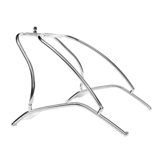
Page 3: Exploded Overview
eXPloded oVerVieW note: lUbrIcAtE pArts wIth A lIGht GrEAsE bEforE AssEmbly tools reQuired GUIDE#: pwb-AIrbornE-v1-004... -
Page 4: Parts List
Parts list TOWER PACKAGE 2.25" TOWER JOINT - THREADED (INCL. M6 X 12mm BOLT) 2.25" TOWER JOINT - THRU HOLE (INCL. M6 X 12mm BOLT) & & & GUIDE#: pwb-AIrbornE-v1-004... - Page 5 Parts list port front lEG stArboArD front lEG port rEAr lEG stArboArD rEAr lEG top sEctIon sIDE rAIls GUIDE#: pwb-AIrbornE-v1-004...
- Page 6 STEP 1 Assemble the side rails to the deck mounts. splIt lock wAshEr note: these should only be loosely tightened at this stage as they will require further adjustment m12 x 45mm lowEr sIDE rAIl in the following stages of assembly. fIttInG m12 x 40mm moUnt...
- Page 7 steP 4 once the desired position is achieved, place one of the large nylon whasers over the piece of tape and trace around it with a permanent marker. STEP 5 Transferring marks from the other side. this step is very important! After taping the second side of the boat in approximately the same areas as the first side you will need to measure the distance that you marked on the first side of the boat...
- Page 8 STEP 6 Drilling once you have marked your 4 holes, check the underside of the deck for wires. If necessary, you should move the wires out of the way while you drill. we recommend drilling a small pilot hole which will keep the 17/32” drill bit from walk- ing (moving).
- Page 9 STEP 7 Install the tower mounts to the boat deck in the order shown in the diagram. Note: in the case where the deck of your boat is less than 1/4” thick, a reinforcing kit is required to thicken and reinforce the deck in the mounting locations. CURVED DECK - MOUNT ASSEMBLY FLAT DECK - MOUNT ASSEMBLY m12 x 75mm...
- Page 10 STEP 8 - CONTINUED... the side rails need to be mounted straight up and down. If they are leaning in or out, this will cause a problem with the tower when you want to fold it. steP 9 splIt lock rEAr lEG wAshEr m12 x 40mm...
- Page 11 STEP 11 make sure that there are no burrs on the inside of the top section tubes. someone will need to hold the top section for you as you insert the front arms into the top section and con- nect the hinge fittings into the side rails. *** IMPORTANT NOTES *** - Lubricate telescopic parts with a light grease before sliding together.
- Page 12 STEP 12 - CONTINUED... Use a smaller bit to make a pilot hole, then use your 27/64” bit. STEP 13 After each hole is drilled, insert the 4 bolts into the top section to keep it from moving. once all bolts are in place, tighten them with a socket wrench and an Allen key.
- Page 13 STEP 14 - LOCKING ThE ROTATING FITTINGS once you are happy with your tower installation and all of the fittings are lined up to allow the tower to fold and function correctly it will then be important to firmly lock the rotating fittings in place to prevent any unwanted rota- tion or loosening.
- Page 14 installing tHe naVigation ligHt the navigation light is shipped separately. It is designed to be installed on the top of the tow point. for a clean wiring installation the wires supplied can be passed through the center of the tow point, along the inside of the top section and down inside the leg tube.
Need help?
Do you have a question about the Airborne Wakeboard Tower and is the answer not in the manual?
Questions and answers