Table of Contents
Advertisement
Advertisement
Table of Contents

Subscribe to Our Youtube Channel
Related Manuals for Balluff BTL5-T1 M P-S103 Series


Summary of Contents for Balluff BTL5-T1 M P-S103 Series
- Page 1 BTL5-T1 _ _ -M _ _ _ _ -P-S103 User’s Guide english...
- Page 2 www.balluff.com...
-
Page 3: Table Of Contents
Starting up the system Operating notes Default setting Presettings 5.4.1 Station address 5.4.2 Bus termination 5.4.3 LED display for Profibus encoder profile Technical data Accuracy Ambient conditions Supply voltage (external) Control signals Magnet Dimensions, weights Connection to the evaluation unit www.balluff.com english... - Page 4 BTL5-T1 _ _ -M _ _ _ _ -P-S103 Magnetostrictive Linear Position Sensor – Profile Style Accessories Captive magnets BTL2-GS10-_ _ _ _-A joint rod Floating magnets Connectors and cables 7.4.1 Connector, freely configurable 7.4.2 Connector, preassembled 7.4.3 Connecting cable, preassembled 7.4.4 Bus termination resistance, freely configurable 7.4.5 Transparent cover 7.4.6 Screw plugs Type code...
-
Page 5: Notes To The User
Software high-frequency fields GSD file via download on the Internet at Severity level 3 EN 61000-4-6 www.balluff.com or e-mail to service@balluff.de. – Magnetic fields EN 61000-4-8 Severity level 4 More detailed information on the guidelines, approvals, and standards is included in the declaration of conformity. -
Page 6: Safety
Flawless function in accordance with the specifications in are structured as follows: the technical data is ensured only when using original SIGNAL WORD Balluff accessories. Use of any other components will void the warranty. Type and source of the hazard Consequences if not complied with... -
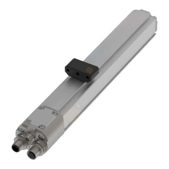
Page 7: Construction And Function
The magnet defines the position to be measured on the Fig. 3-2: Distance between the magnets waveguide. An internally generated INIT pulse interacts with the magnetic field of the magnet to generate a torsional wave in the waveguide which propagates at ultrasonic velocity. www.balluff.com english... -
Page 8: Installation And Connection
BTL5-T1 _ _ -M _ _ _ _ -P-S103 Magnetostrictive Linear Position Sensor – Profile Style Installation and connection Installing the BTL Captive magnets Note when installing the magnet: NOTICE – Avoid lateral forces. – Connect the magnet to the machine member with a Improper installation joint rod (see Accessories on page 15). -
Page 9: Floating Magnets
Dimensions and spacing with magnet BTL5-P-3800-2 Fig. 4-8: Dimensions and spacing with BTL5-P-4500-1 electroma- gnet (24 V/100 mA) The measuring range is offset by 4 mm towards the BTL plug (see Fig. 4-8). Fig. 4-5: Dimensions and spacing with magnet BTL5-P-5500-2 www.balluff.com english... -
Page 10: Shielding And Cable Routing
BTL5-T1 _ _ -M _ _ _ _ -P-S103 Magnetostrictive Linear Position Sensor – Profile Style Installation and connection (continued) Shielding and cable routing Noise elimination To avoid equipotential bonding (current flow) through the Defined ground! cable shield, please note the following: The BTL and the control cabinet must be at the –... -
Page 11: Electrical Connection
PROFIBUS-DP Master BKS-S105-R01 BKS-S103/GS103-CP-… # 125 Bus In Bus Out Bus In Bus Out Bus In Bus Out PROFIBUS-DP Interface PROFIBUS-DP Interface PROFIBUS-DP Interface BTL5-T1…-S103 BTL5-T1…-S103 BTL5-T1…-S103 +24 V BKS-S 48-15-CP-… Fig. 4-10: BTL5-T1…-S103 with master, connection example www.balluff.com english... -
Page 12: Startup
BTL5-T1 _ _ -M _ _ _ _ -P-S103 Magnetostrictive Linear Position Sensor – Profile Style Startup Starting up the system Presettings The station address can be configured through the DANGER Set_Slave_Address service. This service requires a class 2 DP master. The linear position sensor’s GSD file is used for Uncontrolled system movement configuration. -
Page 13: Station Address
LED display for Profibus encoder profile If multiple malfunctions are present at the same time, the malfunction with the highest priority is displayed. Detailed configuration instructions can be requested on the Internet at www.balluff.com or via email at service@balluff.de. www.balluff.com english... -
Page 14: Technical Data
: Use in enclosed spaces and up to a height of 2000 m above sea per EN 60068-2-6 4), 5) level. Degree of protection per Individual specifications as per Balluff factory standard IEC 60529 Resonant frequencies excluded when threaded together IP67 : The BTL must be externally connected via a limited-energy circuit as defined in UL 61010-1, a low-power source as defined in... - Page 15 Example: BTL2-GS10-0100-A (nominal length = 100 mm) BTL5-F-2814-1S M5x10 Fig. 7-2: Installation dimensions of BTL5-F-2814-1S magnet Weight: Approx. 28 g Housing: Aluminum Slide surface: Plastic BTL5-T-2814-1S Fig. 7-3: Installation dimensions of BTL5-T-2814-1S magnet Weight: Approx. 28 g Housing: Aluminum Slide surface: Plastic www.balluff.com english...
- Page 16 BTL5-T1 _ _ -M _ _ _ _ -P-S103 Magnetostrictive Linear Position Sensor – Profile Style Accessories (continued) Floating magnets BTL6-A-3801-2 37.6 BTL5-P-3800-2 Ø 4.2 Ø 4.2 Fig. 7-8: Installation dimensions for BTL6-A-3801-2 Weight: Approx. 25 g Fig. 7-5: Installation dimensions of BTL5-P-3800-2 magnet Housing: Plastic Weight: Approx. 12 g...
- Page 17 Cable length 5 m Fig. 7-14: Connector BKS-S48-15-CP-… Ø 20 Fig. 7-11: Connector BKS-S104-00 (socket) for BUS IN BKS-S105-00 Straight connector, freely configurable M12, 5-pole Cable feed-through (pinch ring PG 9) Fig. 7-12: Connector BKS-S105-00 (pin) for BUS OUT www.balluff.com english...
- Page 18 BTL5-T1 _ _ -M _ _ _ _ -P-S103 Magnetostrictive Linear Position Sensor – Profile Style Accessories (continued) 7.4.3 Connecting cable, preassembled 7.4.4 Bus termination resistance, freely configurable BKS-S103/GS103-CP-… Connecting cable, preassembled BKS-S105-R01 M12, 5-pole Bus termination resistance, freely configurable Various cable lengths can be ordered, e.g. BKS-S103/ M12, 5-pole GS103-CP-05: Cable length 5 m Installed resistors...
- Page 19 1 = 1 - 4, can be selected via GSD Nominal length (4-digit): M0500 = Measurements in mm, nominal length 500 mm (M0050…M4000) Construction: P = profile housing Electrical connection: S103 = 1 x 3-pin male 1 x 5-pin male 1 x 5-pin female www.balluff.com english...
- Page 20 BTL5-T1 _ _ -M _ _ _ _ -P-S103 Magnetostrictive Linear Position Sensor – Profile Style Appendix Converting units of length 1 mm = 0.0393700787 inches 1 inch = 25.4 mm inch inch 0.03937008 25.4 0.07874016 50.8 0.11811024 76.2 0.15748031 101.6 0.19685039 0.23622047 152.4 0.27559055 177.8 0.31496063...
Need help?
Do you have a question about the BTL5-T1 M P-S103 Series and is the answer not in the manual?
Questions and answers