Balluff BTL7-A G501-M Series User Manual
Hide thumbs
Also See for BTL7-A G501-M Series:
- User manual (155 pages) ,
- Condensed manual (16 pages) ,
- User manual (26 pages)
Table of Contents
Advertisement
Quick Links
Advertisement
Table of Contents

Related Manuals for Balluff BTL7-A G501-M Series


Summary of Contents for Balluff BTL7-A G501-M Series
- Page 1 BTL7-A/C/E/G501-M _ _ _ _ -P-S32/S115/KA _ _ User’s Guide english...
- Page 2 www.balluff.com...
- Page 3 Ambient conditions Supply voltage (external) Output Communication lines La, Lb Dimensions, weights Accessories Captive magnets BTL2-GS10-_ _ _ _-A joint rod Floating magnets Connector type S32 8.4.1 Freely configurable 8.4.2 Preassembled Connector type S115, preassembled USB communication box www.balluff.com english...
- Page 4 BTL7-A/C/E/G501-M _ _ _ _ -P-S32/S115/KA _ _ Magnetostrictive Linear Position Sensor – Profile Style Type code Appendix 10.1 Converting units of length 10.2 Part label english...
- Page 5 Severity level 2 – Conducted interference induced by high-frequency fields Severity level 3 EN 61000-4-6 – Magnetic fields EN 61000-4-8 Severity level 4 More detailed information on the guidelines, approvals, and standards is included in the declaration of conformity. www.balluff.com english...
-
Page 6: Signal Word
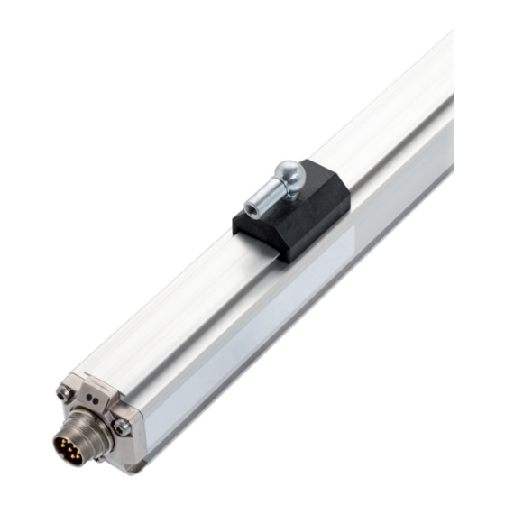
Flawless function in accordance with the specifications in are structured as follows: the technical data is ensured only when using original SIGNAL WORD Balluff accessories. Use of any other components will void the warranty. Hazard type and source Opening the BTL or non-approved use are not permitted... - Page 7 Magnet: Defines the position to be measured on the waveguide. Magnets are available in various models and must be ordered separately (see Accessories on page 18). Nominal length: To optimally adapt the BTL to the application, nominal lengths from 50 mm to 7620 mm are available. www.balluff.com english...
- Page 8 BTL7-A/C/E/G501-M _ _ _ _ -P-S32/S115/KA _ _ Magnetostrictive Linear Position Sensor – Profile Style Construction and function (continued) Function LED display The BTL contains the waveguide which is protected by an aluminum housing. A magnet is moved along the LED 1 LED 2 waveguide.
- Page 9 (see Fig. 4-1 to Fig. 4-3). Fig. 4-2: Dimensions and distances with BTL5-T-2814-1S magnet Fig. 4-3: Dimensions and distances with BTL5-M/N-2814-1S magnet BTL5-M-2814-1S BTL5-N-2814-1S Distance X 48.5 mm 57 mm Distance Y 51 mm 59.5 mm Tab. 4-1: Distances with BTL5-M/N-2814-1S magnet www.balluff.com english...
- Page 10 BTL7-A/C/E/G501-M _ _ _ _ -P-S32/S115/KA _ _ Magnetostrictive Linear Position Sensor – Profile Style Installation and connection (continued) Floating magnets The following must be observed when installing the magnet: – To ensure the accuracy of the position measuring system, the magnet is attached to the moving member of the machine using non-magnetizable screws (stainless steel, brass, aluminum).
-
Page 11: Electrical Connection
Tab. 4-4: Connection assignment BTL7-…-S115 Unassigned leads can be connected to the GND on the controller side but not to the shield. Factory setting, can be freely configured with the PC software. Reference potential for supply voltage and EMC-GND. www.balluff.com english... -
Page 12: Magnetic Fields
BTL7-A/C/E/G501-M _ _ _ _ -P-S32/S115/KA _ _ Magnetostrictive Linear Position Sensor – Profile Style Installation and connection (continued) Shielding and cable routing Defined ground! The BTL and the control cabinet must be at the same ground potential. Shielding To ensure electromagnetic compatibility (EMC), observe the following: –... - Page 13 BTL or after repair by the manufacturer. Operating notes – Regularly check function of the BTL and all associated components. – Take the BTL out of operation whenever there is a malfunction. – Secure the system against unauthorized use. www.balluff.com english...
- Page 14 – Demo mode without a connected BTL Controller The PC software and associated 8-pin manual can be found in the Internet under www.balluff.com. USB cable Connection cable approx. 0.6 m with luster terminal Fig. 6-2: Connecting the communication box with a cable connection When reading or writing data via the Configuration Tool, both LEDs flash green.
- Page 15 – Speed (no sign): speed of the magnet. The direction of movement cannot be read. Max. detectable speed range of 0 to 10 m/s. – Differential position: Distance between two magnets. Selection is only possible if two magnets have been selected. www.balluff.com english...
-
Page 16: Ambient Conditions
For UL: Use in enclosed spaces and up to a height of 2000 m above sea Continuous shock 150 g/2 ms level. per EN 60068-2-27 5), 6) Individual specifications as per Balluff factory standard Vibration 20 g, 10…2000 Hz Resonant frequencies excluded per EN 60068-2-6 5), 6) -
Page 17: Dimensions / Weights
Dimensions, weights Housing height 36.8 mm Nominal length 50…7620 mm Weight (depends on length) Approx. 1.4 kg/m Housing material Aluminum BTL7-…-KA_ _ Cable material cULus 20549 80 °C, 300 V, internal wiring Cable temperature –40°C…+90°C Cable diameter Max. 7 mm Permissible bending radius Fixed routing ≥ 35 mm Moved ≥ 105 mm www.balluff.com english... - Page 18 BTL7-A/C/E/G501-M _ _ _ _ -P-S32/S115/KA _ _ Magnetostrictive Linear Position Sensor – Profile Style Accessories Captive magnets BTL2-GS10-_ _ _ _-A joint rod Nominal length BTL5-M/N-2814-1S Mechanically joined to M5 stud using 2 nuts Adjustment range −5 mm Fig. 8-1: Installation dimensions of BTL5-M/N-2814-1S magnet Fig.
- Page 19 Special advantage of the BTL5-P-4500-1 magnet: Several magnets on the same BTL can be separately switched on and off electrically (actuation BTL6-A-3800-2 with a PLC signal). 37.6 Ø 4.2 Fig. 8-7: Installation dimensions of BTL6-A-3800-2 magnet Weight: Approx. 30 g Housing: Plastic www.balluff.com english...
- Page 20 BTL7-A/C/E/G501-M _ _ _ _ -P-S32/S115/KA _ _ Magnetostrictive Linear Position Sensor – Profile Style Accessories (continued) Connector type S32 8.4.2 Preassembled Straight connector, molded, M16, 8-pin Various cable lengths can be ordered, e.g. 8.4.1 Freely configurable BCC S518-0000-1Y-133-PS0825-050 (Order code: BCC0L21): Cable length 5 m BKS-S 32M-00 Order code: BCC00TT Straight connector, M16 per IEC 130-9, 8-pin...
- Page 21 BKS-S116-PU-05 (Order code: BCC00YW): Cable length 5 m M12x1 Fig. 8-15: Connector BKS-S116-PU-_ _ Fig. 8-16: Connector BKS-S116-PU-_ _, outlet Color YE yellow GY gray PK pink RD red GN green BU blue BN brown WH white Tab. 8-2: BKS-S115/S116-PU-_ _ pin assignment www.balluff.com english...
- Page 22 BTL7-A/C/E/G501-M _ _ _ _ -P-S32/S115/KA _ _ Magnetostrictive Linear Position Sensor – Profile Style Type code BTL7 - A 5 01 - M0500 - P - S32 Interface: A = Analog interface, voltage output 0…10 V / 10…0 V (factory setting) G = Analog interface, voltage output 10…10 V / 10…–10 V (factory setting) C = Analog interface, current output 0…20 mA / 20…0 mA (factory setting) E = Analog interface, current output 4…20 mA / 20…4 mA (factory setting)
- Page 23 152.4 0.27559055 177.8 0.31496063 203.2 0.35433071 228.6 0.393700787 Tab. 10-1: Conversion table mm to inches Tab. 10-2: Conversion table inches to mm 10.2 Part label Order code Type Serial number Null mark Fig. 10-1: BTL7 part label (example) www.balluff.com english...
Need help?
Do you have a question about the BTL7-A G501-M Series and is the answer not in the manual?
Questions and answers